Kia Cadenza YG: Automatic Transaxle Control System / Underdrive Brake Control Solenoid Valve(UD/B_VFS) Repair procedures
Kia Cadenza YG 2016-2021 Service Manual / Automatic Transaxle System / Automatic Transaxle Control System / Underdrive Brake Control Solenoid Valve(UD/B_VFS) Repair procedures
| Inspection |
| 1. |
Turn ignition switch OFF. |
| 2. |
Remove the battery and battery tray.
(Refer to Engine Electrical System - "Battery") |
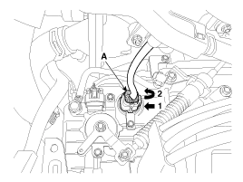
| 3. |
Disconnect the solenoid valve connector (A).
|
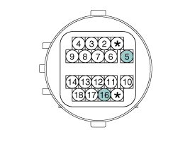
| 4. |
Measure the resistance between power terminal (5) and signal terminal (16).
|
| Replacement |
If a solenoid valve of VFS type needs to be replaced, the
valve body assembly should be replaced and the oil pressure should be
adjusted. If the solenoid valve is replaced individually, it is not
possible to adjust the oil pressure without additional equipment, and if
the oil pressure adjustment procedure is not performed, a shift shock
or delay may occur. |

| 1. |
Replace the valve body assembly.
(Refer to Hydraulic System - "Valve Body") |
Specification Item SpecificationControl typeN/H (Normal High)Control pressure kpa (kgf/cm², psi)"500.14 ~ 9.81 (5.1 ~ 0.1, 72.54 ~ 1.42)"Current value (mA)50 ~ 850Coil resistance(Ω)5.
Other information:
Kia Cadenza YG 2016-2021 Service Manual: Components and Components Location
C
Kia Cadenza YG 2016-2021 Service Manual: Description and Operation
Description The immobilizer system will disable the vehicle unless the proper ignition key is used, in addition to the currently available anti-theft systems such as car alarms, the immobilizer system aims to drastically reduce the rate of auto theft.
Categories
- Manuals Home
- Kia Cadenza Owners Manual
- Kia Cadenza Service Manual
- Body (Interior and Exterior)
- Restraint
- Timing Chain Repair procedures
- New on site
- Most important about car

Copyright © 2026 www.kcadenzavg.com - 0.0236