Kia Cadenza YG: Hydraulic System / Valve Body Components and Components Location
Kia Cadenza YG 2016-2021 Service Manual / Automatic Transaxle System / Hydraulic System / Valve Body Components and Components Location
| Components Location |
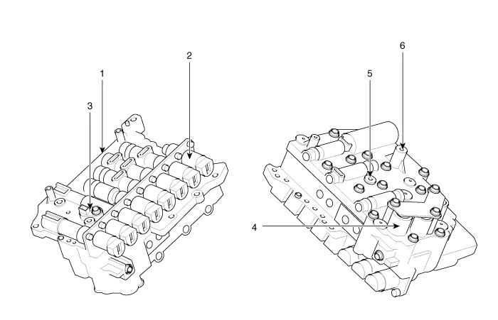
| 1. PCV adjust screw 2. Solenoid valve 3. Oil temperature sensor | 4. Accumulator 5. Low & reverse brake(LR/B) pressure flow hole 6. Under drive brake (UD/B) pressure flow hole |
Valve Body Flow
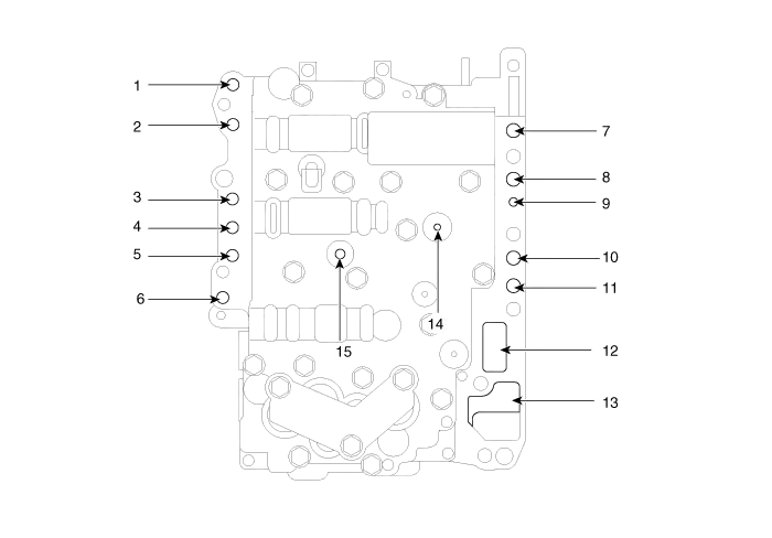
| 1. To cooler 2. From cooler 3. Lubrication(rear) 4. Overdrive pressure 5. Reducing pressure (red2) 6. Reducing pressure (red1) 7. From damper pressure 8. To damper pressure | 9. Lubrication(front) 10. 35R clutch pressure 11. 26 brake pressure 12. From oil pump 13. To oil pump 14. Underdrive pressure 15. Low & reverse pressure |
Description The valve body is essential to automatic transaxle control and consists of various valves used to control the oil feed from the oil pump.
Removal 1. Remove the under cover. (Refer to Engine Mechanical System - "Engine Room Under Cover"). 2. Remove the ATF drain plug (A), allow the fluid to drain out and then reinstall the drain plug.
Categories
- Manuals Home
- Kia Cadenza Owners Manual
- Kia Cadenza Service Manual
- Components and Components Location
- Battery Troubleshooting
- Emission Control System
- New on site
- Most important about car

Copyright © 2026 www.kcadenzavg.com - 0.0272