Kia Cadenza YG: Hydraulic System / Valve Body Repair procedures
Kia Cadenza YG 2016-2021 Service Manual / Automatic Transaxle System / Hydraulic System / Valve Body Repair procedures
| Removal |
| 1. |
Remove the under cover.
(Refer to Engine Mechanical System - "Engine Room Under Cover"). |
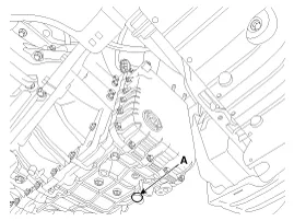
| 2. |
Remove the ATF drain plug (A), allow the fluid to drain out and then reinstall the drain plug.
|

| 3. |
Remove the battery and battery tray.
(Refer to Engine Electrical System - "Battery") |
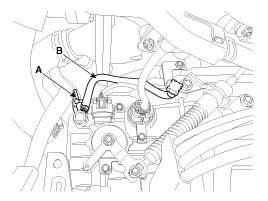
| 4. |
Remove the wiring bracket (A) and the air breather hose (B).
|
| 5. |
Lift the vehicle after loosening valve body cover upper bolts. |
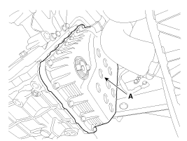
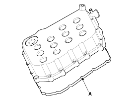
| 6. |
Remove the valve body cover (A) by loosening bolts.
|
| 7. |
Remove the solenoid valve harness (A) and oil temperature sensor (B) after removing the bolts.
|
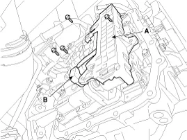
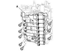
| 8. |
Remove the valve body assembly (A).
|
| Installation |
| 1. |
Install in the reverse order of removal.
|
Components Location 1. PCV adjust screw2. Solenoid valve3. Oil temperature sensor4. Accumulator5. Low & reverse brake(LR/B) pressure flow hole6.
Categories
- Manuals Home
- Kia Cadenza Owners Manual
- Kia Cadenza Service Manual
- Body Electrical System
- Restraint
- Suspension System
- New on site
- Most important about car

Copyright © 2026 www.kcadenzavg.com - 0.0212