Kia Cadenza YG: Automatic Transaxle Control System / Output Speed Sensor Repair procedures
| Inspection |
| 1. |
Turn ignition switch OFF. |
| 2. |
Remove the battery and battery tray.
(Refer to Engine Electrical System - "Battery") |
| 3. |
Disconnect the solenoid valve connector (A).
|
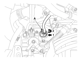
| 4. |
Measure the resistance between power terminal (3) and signal terminal (4).
|
| Removal |
| 1. |
Remove the valve body assembly.
(Refer to Hydraulic System - "Valve Body") |
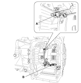
| 2. |
Disconnect the input & output speed sensor connector (A). |
| 3. |
Remove the input & output speed sensor (B) after loosening the bolts.
|
| Installation |
| 1. |
Install in the reverse order of removal.
|

Signal Waveform Fig 1) Input/Output speed sensor at low speed Fig 2) Input/Output speed sensor at high speed
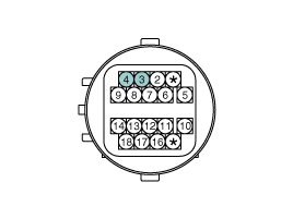
Specification Item SpecificationControl typeN/L (Normal Low)Control pressure kpa (kgf/cm², psi)"9.81 ~ 500.14 (0.1 ~ 5.1, 1.42 ~ 72.54)"Current value (mA)50 ~ 850Coil resistance(Ω)5.
Other information:
Kia Cadenza YG 2016-2021 Service Manual: Pantoscopic Camera Repair procedures
Removal Front Pantoscopic Camera 1. Disconnect the negative (-) battery terminal. 2. Remove the front bumper cover. (Refer to Body - "Front Bumper Cover") 3. Remove the pantocscpic camera (B) after loosening the mounting screws and connector (A).
Kia Cadenza YG 2016-2021 Service Manual: Compressor Repair procedures
Removal 1. If the compressor is marginally operable, run the engine at idle speed, and let the air conditioning work for a few minutes, then shut the engine off. 2. Disconnect the negative cable from the battery. 3. Recover the refrigerant with a recovery/charging station.
Categories
- Manuals Home
- Kia Cadenza Owners Manual
- Kia Cadenza Service Manual
- Emission Control System
- Schematic Diagrams
- Components and Components Location
- New on site
- Most important about car
