Kia Cadenza YG: Cylinder Block / Piston and Connecting Rod Components and Components Location
Kia Cadenza YG 2016-2021 Service Manual / Engine Mechanical System / Cylinder Block / Piston and Connecting Rod Components and Components Location
| Components |
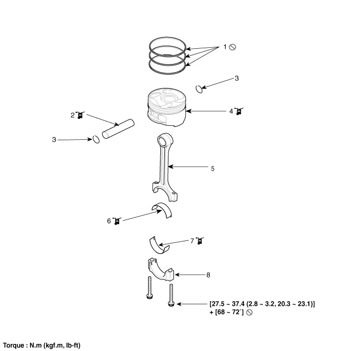
| 1. Piston ring 2. Piston pin 3. Snap ring 4. Piston | 5. Connecting rod 6. Connecting rod upper bearing 7. Connecting rod lower bearing 8. Connecting rod bearing cap |
Removal 1. Remove the transaxle assembly. (Refer to Automatic Transaxle System - "Automatic Transaxle") 2. Remove the drive plate. (Refer to Cylinder Block - "Drive Plate") 3.
Disassembly • Use fender covers to avoid damaging painted surfaces. • To avoid damage, unplug the wiring connectors carefully while holding the connector portion.
Other information:
Kia Cadenza YG 2016-2021 Service Manual: Pantoscopic Camera Components and Components Location
C
Kia Cadenza YG 2016-2021 Service Manual: Specifications
Specification ItemSpecificationUltrasonic sensorVoltage ratingDC 12 VDetecting range30 cm ~ 120 cmOperation voltageDC 9 ~ 16 VOperation currentMAX 300 mAOperation temperature-30°C ~ +80°C (-22°C ~ +176°C)Operation frequency48 ± 5 KHzEffective operating velocity10 KPH (6.
Categories
- Manuals Home
- Kia Cadenza Owners Manual
- Kia Cadenza Service Manual
- Engine Electrical System
- Body Electrical System
- Steering System
- New on site
- Most important about car

Copyright © 2026 www.kcadenzavg.com - 0.0214