Kia Cadenza YG: Engine Control System / Purge Control Solenoid Valve (PCSV) Repair procedures
| Inspection |
| 1. |
Turn the ignition switch OFF. |
| 2. |
Disconnect the PCSV connector. |
| 3. |
Measure resistance between the PCSV terminals 1 and 2. |
| 4. |
Check that the resistance is within the specification.
|
| Removal |
| 1. |
Turn the ignition switch OFF and disconnect the battery negative (-) cable. |
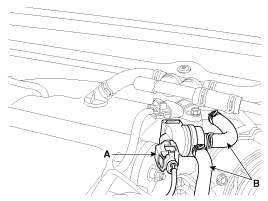
| 2. |
Disconnect the purge control solenoid valve connector (A). |
| 3. |
Disconnect the vapor hoses (B) from the purge control solenoid valve. |
| 4. |
Remove the valve from the bracket.
|
| Installation |
|

|
| 1. |
Install in the reverse order of removal.
|
Circuit Diagram
Description Continuous Variable Valve Timing (CVVT) system advances or retards the valve timing of the intake and exhaust valve in accordance with the ECM control signal which is calculated by the engine speed and load.
Other information:
Kia Cadenza YG 2016-2021 Service Manual: Description and Operation
Description Surround View Monitoring System (SVM) is the system that allows video monitoring of 360 degrees around the vehicle. The system includes 4 ultra optical camera mounted around the vehicle (front, both sides, rear). The video from these cameras are applied with distortion compensation, time point conversion, and video merging
Kia Cadenza YG 2016-2021 Service Manual: Photo Sensor Repair procedures
Inspection 1. Ignition "ON" 2. Using the scan tool. 3. Emit intensive light toward photo sensor using a lamp, and check the output voltage change. 4. The voltage will rise with higher intensive light and reduce with lower intensive light.
Categories
- Manuals Home
- Kia Cadenza Owners Manual
- Kia Cadenza Service Manual
- Emission Control System
- General Information
- Steering System
- New on site
- Most important about car
