Kia Cadenza YG: Electric Power Steering / Schematic Diagrams
| MDPS Circuit Diagram |
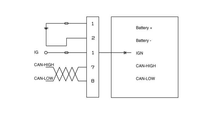
| Type | Pin No | Description |
| Battery | 1 | Battery + |
| 2 | Battery - | |
| Vehicle | 1 | IGN |
| 2 | - | |
| 3 | - | |
| 4 | - | |
| 5 | - | |
| 6 | - | |
| 7 | High_CAN | |
| 8 | Low_CAN |
Components 1. Steering column2. ECU3. Motor4. Steering gear box
General Inspection After or before servicing the EPS system, perform the troubleshooting and test procedure as follows. Compare the system condition with normal condition in the table below and if abnormal symptom is detected, perform necessary remedy and inspection.
Other information:
Kia Cadenza YG 2016-2021 Service Manual: A/C Pressure Transducer Description and Operation
Description A/C pressure transducer convert the pressure value of high pressure line into voltage value after measure it. By converted voltage value, engine ECU controls cooling fan by operating it high speed or low speed. Engine ECU stop the operation of compressor when the temperature of refrigerant line is so high or so low irregularl
Kia Cadenza YG 2016-2021 Service Manual: Cluster ionizer Description and Operation
Description 1. The function of cluster ion generator is cleaning air by sterilizing and dissolving of air conditioner. 2. The function of cluster ion generator is controlling mold caused by stench of air conditioner and external inflow of air.
Categories
- Manuals Home
- Kia Cadenza Owners Manual
- Kia Cadenza Service Manual
- Engine Control / Fuel System
- Engine Mechanical System
- Specifications
- New on site
- Most important about car
