Kia Cadenza YG: Front Suspension System / Front Stabilizer Bar Repair procedures
| Replacement |
| 1. |
Remove the front wheel & tire.
|


| 2. |
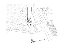
Loosen the bolt (A) and then disconnect the universal joint assembly from the pinion of the steering gear box.
|
| 3. |
Remove the under cover (A).
|

| 4. |
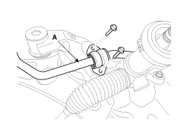
Remove the sprit pin and castle nut and then disconnect the tie-rod end (A) from the front knuckle.
|

| 5. |
Loosen the bolt & nut and then remove the lower arm (A).
|

| 6. |
Remove the front lower arm from the front knuckle using the SST (0K545-A9100).
|


| 7. |
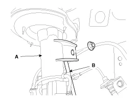
Disconnect the stabilizer link (B) with the front strut assembly (A) after loosening the nut.
|
| 8. |
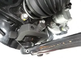
Loosen the bolt and then remove the front roll stopper (A).
|

| 9. |
Disconnect the muffler rubber hanger (A).
|

| 10. |
Loosen the bolts & nuts and then remove the sub frame.
|

| 11. |
Loosen the mounting bolt and then remove the stabilizer bar (B) from the sub frame (A).
|

| 12. |
from the stabilizer bar.
|

| 13. |
Installation is the reverse of removal. |
| Inspection |
| 1. |
Check the bushing for wear and deterioration. |
| 2. |
Check the front stabilizer bar for deformation. |
| 3. |
Check the front stabilizer link ball joint for damage. |
Replacement 1. Remove the front wheel & tire. Tightening torque: 88.3 ~ 107.9N.m (9.0 ~ 11.0kgf.m, 65.1 ~ 79.6lb-ft) Be careful not to damage to the hub bolts when removing the front wheel & tire.
Replacement 1. Remove the front wheel & tire. Tightening torque: 88.3 ~ 107.9N.m (9.0 ~ 11.0kgf.m, 65.1 ~ 79.6lb-ft) Be careful not to damage to the hub bolts when removing the front wheel & tire.
Other information:
Kia Cadenza YG 2016-2021 Service Manual: Blind Spot Detection Variant Coding Description and Operation
Description The used radar frequency of BSD is two, "North America region" and "Except North America region". If it replaces BSD unit, BSD unit has to perform the procedure of variant coding. BSD Variant Coding 1. Select the "BSD Variant Coding" procedure in BSD system.
Kia Cadenza YG 2016-2021 Service Manual: Heater & A/C Control Unit (DATC) Repair procedures
Inspection Self diagnosis 1. Self-diagnosis process 2. How to read self-diagnostic code. After the display panel flickers three times every 0.5 second, the corresponding fault code flickers on the setup temperature display panel every 0.
Categories
- Manuals Home
- Kia Cadenza Owners Manual
- Kia Cadenza Service Manual
- Body (Interior and Exterior)
- Body Electrical System
- Engine Mechanical System
- New on site
- Most important about car
