Kia Cadenza YG: Electric Power Steering / Repair procedures
Kia Cadenza YG 2016-2021 Service Manual / Steering System / Electric Power Steering / Repair procedures
| General Inspection |
After or before servicing the EPS system, perform the
troubleshooting and test procedure as follows. Compare the system
condition with normal condition in the table below and if abnormal
symptom is detected, perform necessary remedy and inspection.
| Test condition | Normal condition: Motor must not supply steering assist. | ||
| Symptom | Possible cause | Remedy | |
| IG Off | Motor supplies steering assist. | ASP is not calibrated. | Perform the ASP calibration using a scan tool. |
| IG power supplies | Inspect the IG power supply line. | ||
| Test condition | Normal condition: Motor must not supply steering assist, Warning lamp is illuminated. | ||
| Symptom | Possible cause | Remedy | |
| IG On/Engine Off | Motor supplies steering assist. | ASP is not calibrated. | Perform the ASP calibration using a scan tool. |
| EMS CAN signal is not received. | Inspect the CAN line. | ||
| Warning lamp is not illuminated. | Cluster fault | Inspect the cluster and cluster harness | |
| Test condition | Normal condition: Motor supplies steering assist, Warning lamp is not illuminated. | ||
| Symptom | Possible cause | Remedy | |
| IG On/Engine On | Warning lamp is illuminated and Motor dose not supply steering assist. | EPS (Hot at all times) and IG power supply fault | Inspect the connector and harness for EPS (Hot at all times) and IG power supply line. |
| DTC is detected by system. | Perform the self test using a scan tool and repair or replace. | ||
| Warning lamp is illuminated and Motor supplies steering assist. | ASP is not calibrated. | Perform the ASP calibration using a scan tool. | |
| CAN communication between EPS and cluster is fault. | Inspect the CAN line. | ||
ASP: Absolute Steering Position
CAN: Controller Area Network
EMS: Engine Management System
The following symptoms may occur during normal vehicle
operation and if there is no EPS warning light illumination, it is not
malfunction of EPS system.
|

Caution when ASP (Absolute Steering Position) calibration or EPS type recognition
| • |
Check if the battery is fully charged before ASP calibration or EPS type recognition. |
| • |
Be careful not to disconnect any cables connected to the vehicle or scan tool during ASP calibration or EPS type recognition. |
| • |
When the ASP calibration or EPS type recognition is
completed, turn the ignition switch off and wait for several seconds,
then start the engine to confirm normal operation of the vehicle. |
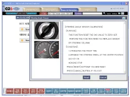
ASP Calibration
| 1. |
Select "Steering Angle Sensor". |
| 2. |
Proceed with the test according to the screen introductions.
|
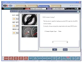
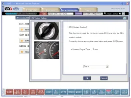
EPS Type Recognition Procedure
| 1. |
Select "EPS Variant Coding". |
| 2. |
Proceed with the test according to the screen introductions.
|
MDPS Circuit Diagram Harness Connector TypePin NoDescriptionBattery1Battery +2Battery -Vehicle1IGN2-3-4-5-6-7High_CAN8Low_CAN
Replacement 1. Disconnect the battery negative cable from the battery and then wait for at least 30 seconds. 2. Turn the steering wheel so that the front wheels can face straight ahead.
Other information:
Kia Cadenza YG 2016-2021 Service Manual: Components and Components Location
C
Kia Cadenza YG 2016-2021 Service Manual: Heater & A/C Control Unit (DATC) Repair procedures
Inspection Self diagnosis 1. Self-diagnosis process 2. How to read self-diagnostic code. After the display panel flickers three times every 0.5 second, the corresponding fault code flickers on the setup temperature display panel every 0.
Categories
- Manuals Home
- Kia Cadenza Owners Manual
- Kia Cadenza Service Manual
- Body (Interior and Exterior)
- Timing Chain Repair procedures
- Restraint
- New on site
- Most important about car

Copyright © 2026 www.kcadenzavg.com - 0.0178