Kia Cadenza YG: Seat Electrical / Seat Heater Components and Components Location
Kia Cadenza YG 2016-2021 Service Manual / Body Electrical System / Seat Electrical / Seat Heater Components and Components Location
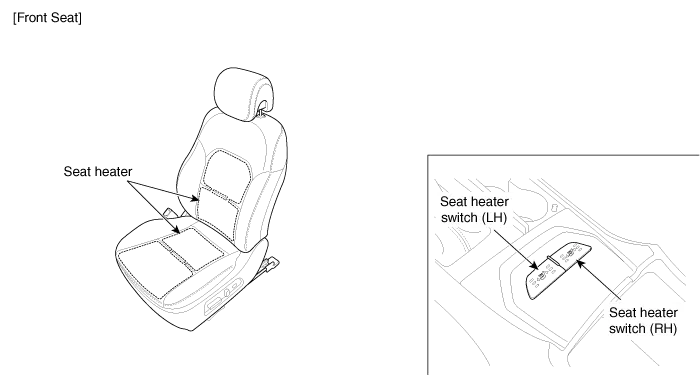
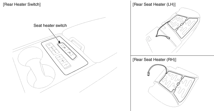
| Component Location |
Inspection With the power seat switch in each position, make sure that continuity exists between the terminals below. If continuity is not as specified, replace the power seat switch.
Circuit Diagram
Other information:
Kia Cadenza YG 2016-2021 Service Manual: Specifications
S
Kia Cadenza YG 2016-2021 Service Manual: Ambient Sensor Repair procedures
Inspection 1. Ignition "OFF" 2. Disconnect ambient temperature sensor. 3. Check the resistance of ambient temperature sensor between terminals 1 and 2 whether it is changed by changing of the ambient temperature. 1. Sensor Ground2.
Categories
- Manuals Home
- Kia Cadenza Owners Manual
- Kia Cadenza Service Manual
- Engine Electrical System
- Timing Chain Repair procedures
- Restraint
- New on site
- Most important about car

Copyright © 2026 www.kcadenzavg.com - 0.0209