Kia Cadenza YG: Smart Cruise Control System / Smart Cruise Control Switch Components and Components Location
Kia Cadenza YG 2016-2021 Service Manual / Engine Electrical System / Smart Cruise Control System / Smart Cruise Control Switch Components and Components Location
| Components |
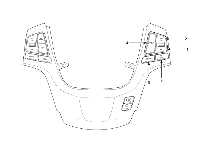
| 1. SET - switch 2. RES + switch 3. SCC switch | 4. CANCEL switch 5. CRUISE switch |
Removal 1. Turn the ignition switch OFF and disconnect the battery negative (-) cable. 2. Remove the front bumper. (Refer to Body - "Front Bumper") 3.
Circuit Diagram
Other information:
Kia Cadenza YG 2016-2021 Service Manual: Repair procedures
Teaching Procedures 1. Key Teaching Procedure Key teaching must be done after replacing a defective PCM(ECM) or when providing additional keys to the vehicle owner. The procedure starts with an PCM(ECM) request for vehicle specific data (PIN code: 6digits) from the tester.
Kia Cadenza YG 2016-2021 Service Manual: Ambient Sensor Repair procedures
Inspection 1. Ignition "OFF" 2. Disconnect ambient temperature sensor. 3. Check the resistance of ambient temperature sensor between terminals 1 and 2 whether it is changed by changing of the ambient temperature. 1. Sensor Ground2.
Categories
- Manuals Home
- Kia Cadenza Owners Manual
- Kia Cadenza Service Manual
- Engine Mechanical System
- Engine Electrical System
- Emission Control System
- New on site
- Most important about car

Copyright © 2026 www.kcadenzavg.com - 0.0297