
Kia Cadenza YG: Smart Cruise Control System / Smart Cruise Control Switch Schematic Diagrams
| Circuit Diagram |
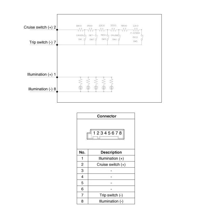
Components 1. SET - switch2. RES + switch3. SCC switch4. CANCEL switch5. CRUISE switch
Inspection [Measuring Resistance] 1. Disconnect the cruise control switch connector from the control switch. 2. Measure resistance between terminals on the control switch when each function switch is ON (switch is depressed).
Other information:
Kia Cadenza YG 2016-2021 Service Manual: Repair procedures
Teaching Procedures 1. Key Teaching Procedure Key teaching must be done after replacing a defective PCM(ECM) or when providing additional keys to the vehicle owner. The procedure starts with an PCM(ECM) request for vehicle specific data (PIN code: 6digits) from the tester.
Kia Cadenza YG 2016-2021 Service Manual: Troubleshooting
Troubleshooting Problem Symptoms Table Before replacing or repairing air conditioning components, first determine if the malfunction is due to the refrigerant charge, air flow or compressor. Use the table below to help you find the cause of the problem.
Categories
- Manuals Home
- Kia Cadenza Owners Manual
- Kia Cadenza Service Manual
- Body Control Module (BCM) Description and Operation
- Components and Components Location
- Schematic Diagrams
- New on site
- Most important about car
