Kia Cadenza YG: Smart Cruise Control System / Smart Cruise Control Switch Repair procedures
Kia Cadenza YG 2016-2021 Service Manual / Engine Electrical System / Smart Cruise Control System / Smart Cruise Control Switch Repair procedures
| Inspection |
[Measuring Resistance]
| 1. |
Disconnect the cruise control switch connector from the control switch.
|
| 2. |
Measure resistance between terminals on the control switch when each function switch is ON (switch is depressed).
|
| 3. |
If not within specification, replace switch. |
[Measuring Voltage]
| 1. |
Connect the cruise control switch connector to the control switch.
|
| 2. |
Measure voltage between terminals on the harness side connector when each function switch is ON (switch is depressed).
|
| 3. |
If not within specification, inspect the control switch resistance.
The measuring resistance value is not within specification, replace the switch and measure the voltage again. |
| 4. |
If resistance is OK but, measuring voltage is not within
specification, inspect the wiring harness and connectors between the
switch and the ECM. |
| Removal |
| 1. |
Turn ignition switch OFF and disconnect the negative (-) battery cable. |
| 2. |
Remove the air-bag module from the steering wheel.
(Refer to Restraint - "Driver Airbag (DAB) Module and Clock Spring") |
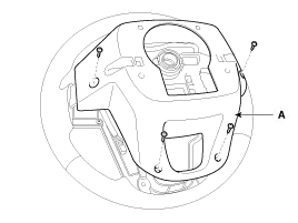
| 3. |
Remove the steering wheel cover (A) after loosening the screws.
|
| 4. |
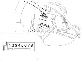
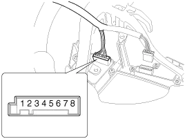
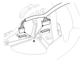
Remove the steering wheel remote control switch connector (A).
[LH]
[RH]
|
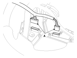
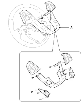
| 5. |
Remove the steering wheel remote control switch (A) after loosening the mounting screws.
|
| Installation |
| 1. |
Install in the reverse order of removal. |
Other information:
Kia Cadenza YG 2016-2021 Service Manual: Blind Spot Detection Unit Repair procedures
Removal 1. Disconnect the negative (-) battery terminal. 2. Remove the rear bumper. (Refer to Body - "Rear Bumper") 3. Remove the BSD unit (A) after loosening the mounting screws. Take care not to separate the bracket from rear bumper when removing the BSD sensor.
Kia Cadenza YG 2016-2021 Service Manual: Heater & A/C Control Unit (DATC) Components and Components Location
C
Categories
- Manuals Home
- Kia Cadenza Owners Manual
- Kia Cadenza Service Manual
- Body (Interior and Exterior)
- Suspension System
- Battery Troubleshooting
- New on site
- Most important about car

Copyright © 2026 www.kcadenzavg.com - 0.0249