Kia Cadenza YG: Smart key System / Smart key unit Schematic Diagrams
| Circuit Diagram |

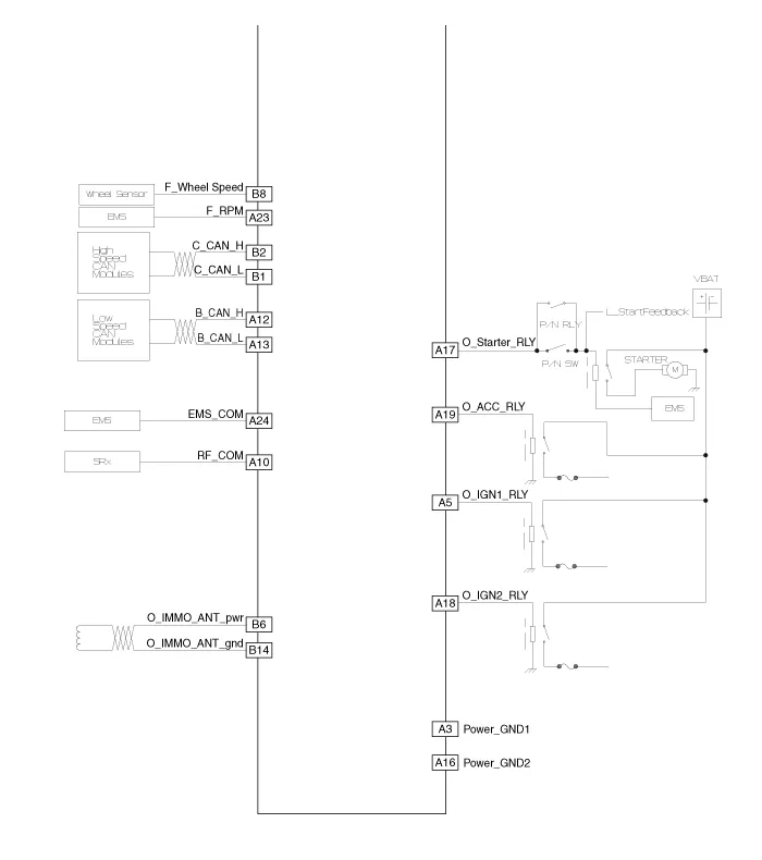
Component (1) Connector Pin Information No.Connector A (26 pins)Connector B (16 pins)Connector C (22 pins)1VBAT loadC CAN lowSSB illumination ground2-C CAN high-3Power ground 1-SSB LED OFF4IGN 1-Interior antenna #2 power5IGN1 relayBrake switchInterior antenna #1 power6ACCImmobilizer antenna power-7IGN 2--8SSB switch 2Wheel speedTrunk antenna power9-Driver toggle buttonBumper antenna power10RF COM-Assist side antena power11--Driver side antenna power12B CAN highP position/ Clutch switchSSB LED IGN13B CAN lowStart feedbackSSB illumination power14VBAT CPUImmobilizer antenna ground-15--Interior antenna #2 ground16Power ground 2SSB LED ACCInterior antenna #1 ground17Starter relay -18IGN2 relay-19ACC relayTrunk antenna ground20-Bumper antenna ground21-Assist side antena ground22-Driver side antenna ground23RPM 24EMS COM25SSB switch 126Assist toggle button Component (2)
Inspection Smart Key Unit – Refer to the BE group - inspection / self diagnosis with GDS. Smart Key Switch – Refer to the BE group - inspection / self diagnosis with GDS.
Other information:
Kia Cadenza YG 2016-2021 Service Manual: Parking Assist Sensor Repair procedures
Removal 1. Disconnect the negative (-) battery terminal. 2. Remove the rear bumper cover. (Refer to Body - "Rear Bumper Cover") 3. Disconnect the connector (A) from the parking assist sensor. 4. Pull out the sensor (A) by opening the sensor holder (B) out.
Kia Cadenza YG 2016-2021 Service Manual: Components and Components Location
Component Location 1. Start Stop Button(SSB)2. FOB key3. RF receiver4. Smart key unit5. Interior antenna 16. Interior antenna 2 7. Trunk antenna8. Bumper antenna9. Door handle & door antenna10. Trunk lid open switch11.
Categories
- Manuals Home
- Kia Cadenza Owners Manual
- Kia Cadenza Service Manual
- Engine Control / Fuel System
- Components and Components Location
- General Information
- New on site
- Most important about car
