Kia Cadenza YG: Smart key System / Smart key unit Components and Components Location
| Component (1) |
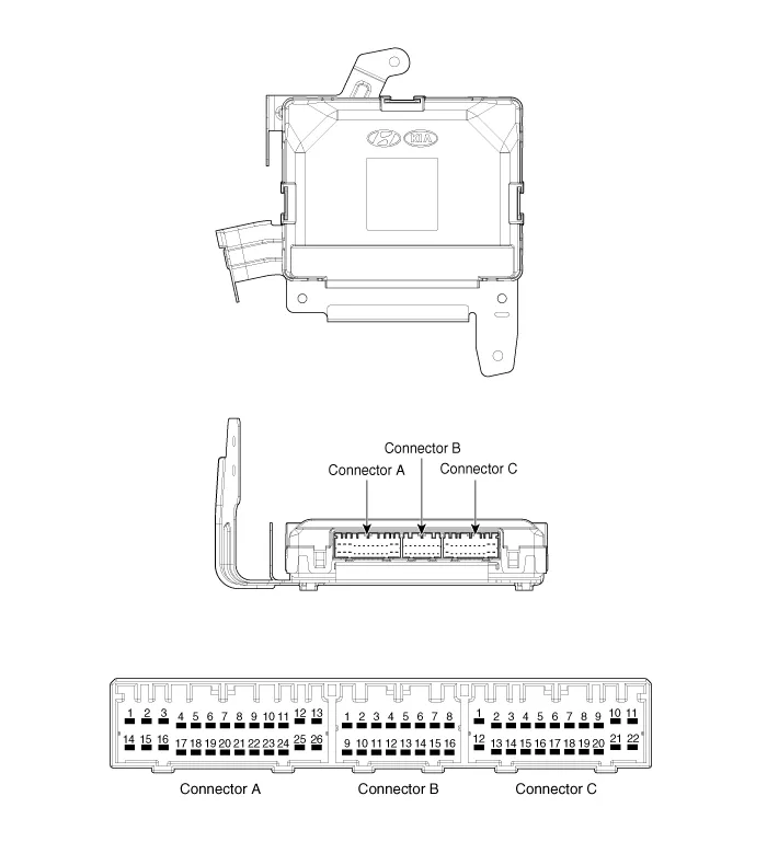
| No. | Connector A (26 pins) | Connector B (16 pins) | Connector C (22 pins) |
| 1 | VBAT load | C CAN low | SSB illumination ground |
| 2 | - | C CAN high | - |
| 3 | Power ground 1 | - | SSB LED OFF |
| 4 | IGN 1 | - | Interior antenna #2 power |
| 5 | IGN1 relay | Brake switch | Interior antenna #1 power |
| 6 | ACC | Immobilizer antenna power | - |
| 7 | IGN 2 | - | - |
| 8 | SSB switch 2 | Wheel speed | Trunk antenna power |
| 9 | - | Driver toggle button | Bumper antenna power |
| 10 | RF COM | - | Assist side antena power |
| 11 | - | - | Driver side antenna power |
| 12 | B CAN high | P position/ Clutch switch | SSB LED IGN |
| 13 | B CAN low | Start feedback | SSB illumination power |
| 14 | VBAT CPU | Immobilizer antenna ground | - |
| 15 | - | - | Interior antenna #2 ground |
| 16 | Power ground 2 | SSB LED ACC | Interior antenna #1 ground |
| 17 | Starter relay | | - |
| 18 | IGN2 relay | - | |
| 19 | ACC relay | Trunk antenna ground | |
| 20 | - | Bumper antenna ground | |
| 21 | - | Assist side antena ground | |
| 22 | - | Driver side antenna ground | |
| 23 | RPM | | |
| 24 | EMS COM | ||
| 25 | SSB switch 1 | ||
| 26 | Assist toggle button |
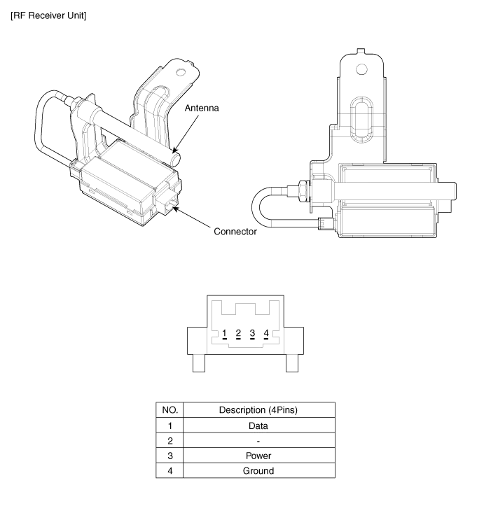
| Component (2) |
Smart Key Smart Key Code Saving 1. Connect the DLC cable of GDS to the data link connector in driver side crash pad lower panel, turn the power on GDS.
Circuit Diagram
Other information:
Kia Cadenza YG 2016-2021 Service Manual: Photo Sensor Description and Operation
Description 1. The photo sensor is located at the center of defrost nozzle. 2. The photo sensor contains a photovoltaic (sensitive to sunlight) diode. The solar radiation received by its light receiving portion, generates an electromotive force in proportion to the amount of radiation received which is transferred to the automatic tem
Kia Cadenza YG 2016-2021 Service Manual: Power Mosfet Repair procedures
Inspection 1. Ignition "ON" 2. Manually operate the control switch and measure the voltage of blower motor. 3. Select the control switch to raise voltage until high speed. Specification FanMotor VoltageManualFirst speed3.8 ±0.5VSecond speed5.
Categories
- Manuals Home
- Kia Cadenza Owners Manual
- Kia Cadenza Service Manual
- Suspension System
- Emission Control System
- Automatic Transaxle System
- New on site
- Most important about car
