Kia Cadenza YG: Surround View Monitoring (SVM) System / Surround View Monitoring Unit Repair procedures
Kia Cadenza YG 2016-2021 Service Manual / Body Electrical System / Surround View Monitoring (SVM) System / Surround View Monitoring Unit Repair procedures
| Removal |
| 1. |
Disconnect the negative (-) battery terminal. |
| 2. |
Remove the glove box housing.
(Refer to Body - "Glove Box Housing") |
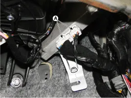
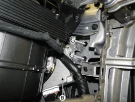
| 3. |
Remove the SVM unit (B) after disconnecting the connectors (A) and mounting bolts.
|
| Installation |
| 1. |
Install the SVM unit. |
| 2. |
Install the glove box housing and glove box. |
| 3. |
Connect the negative (-) battery terminal. |
Other information:
Kia Cadenza YG 2016-2021 Service Manual: Description and Operation
System Overview RPAS (Rear Parking Assist System) is an electronic driving aid that warns the driver to be cautious while parking or in low speed environments. The sensor uses ultrasonic waves to detect objects within proximity of the vehicle.
Kia Cadenza YG 2016-2021 Service Manual: Specifications
S
Categories
- Manuals Home
- Kia Cadenza Owners Manual
- Kia Cadenza Service Manual
- Body Electrical System
- Specifications
- Suspension System
- New on site
- Most important about car

Copyright © 2026 www.kcadenzavg.com - 0.0226