Kia Cadenza YG: Lighting System / Trunk Lamps Repair procedures
| Removal |
| 1. |
Disconnect the negative (-) battery terminal. |
| 2. |
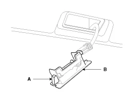
Remove the luggage room lamp (B) when prying the hole (A) with a flat-up screwdriver.
|
| 3. |
Remove the luggage room lamp bulb in case of necessity. |
| Installation |
| 1. |
Install the luggage room lamp assembly after connecting the lamp connector. |
Removal Mood Lamp 1. Disconnect the negative (-) battery terminal. 2. Remove the front door trim. (Refer to Body - "Front Door") 3. Remove the connector and LED mood lamp (A).
Troubleshooting 1. The lamp switch inputs can be checked using the GDS. 2. To check the input value of lamp switch, select option "IPM". 3. To consult the present input/output value of IPM, "Current DATA".
Other information:
Kia Cadenza YG 2016-2021 Service Manual: Description and Operation
Description Adaptive Front-lighting System (AFLS) AFLS(Adaptive Front-lighting System)is a headlamp orientation control system that takes into account both steering angle and vehicle speed to orient the headlamps to an angle that provides better nighttime visibility.
Kia Cadenza YG 2016-2021 Service Manual: Specifications
Specification ItemSpecificationUltrasonic sensorVoltage ratingDC 12 VDetecting range30 cm ~ 120 cmOperation voltageDC 9 ~ 16 VOperation currentMAX 300 mAOperation temperature-30°C ~ +80°C (-22°C ~ +176°C)Operation frequency48 ± 5 KHzEffective operating velocity10 KPH (6.
Categories
- Manuals Home
- Kia Cadenza Owners Manual
- Kia Cadenza Service Manual
- Specifications
- Suspension System
- Alternator Schematic Diagrams
- New on site
- Most important about car
