
Kia Cadenza YG: Automatic Transaxle Control System / Underdrive Brake Control Solenoid Valve(UD/B_VFS) Repair procedures
| Inspection |
| 1. |
Turn ignition switch OFF. |
| 2. |
Remove the battery and battery tray.
(Refer to Engine Electrical System - "Battery") |
| 3. |
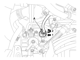
Disconnect the solenoid valve connector (A).
|
| 4. |
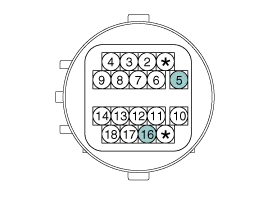
Measure the resistance between power terminal (5) and signal terminal (16).
|
| Replacement |
If a solenoid valve of VFS type needs to be replaced, the
valve body assembly should be replaced and the oil pressure should be
adjusted. If the solenoid valve is replaced individually, it is not
possible to adjust the oil pressure without additional equipment, and if
the oil pressure adjustment procedure is not performed, a shift shock
or delay may occur. |

| 1. |
Replace the valve body assembly.
(Refer to Hydraulic System - "Valve Body") |
Specification Item SpecificationControl typeN/H (Normal High)Control pressure kpa (kgf/cm², psi)"500.14 ~ 9.81 (5.1 ~ 0.1, 72.54 ~ 1.42)"Current value (mA)50 ~ 850Coil resistance(Ω)5.
Other information:
Kia Cadenza YG 2016-2021 Service Manual: Parking Assist Sensor Repair procedures
Removal 1. Disconnect the negative (-) battery terminal. 2. Remove the rear bumper cover. (Refer to Body - "Rear Bumper Cover") 3. Disconnect the connector (A) from the parking assist sensor. 4. Pull out the sensor (A) by opening the sensor holder (B) out.
Kia Cadenza YG 2016-2021 Service Manual: Blower Resistor Repair procedures
Inspection 1. Measure terminal - to - terminal resistance of blower resistor. 2. If measure resistance isnot within specification, the blower resistor must be replaced. Replacement 1. Disconnect the negative (-) battery terminal. 2. Remove the crash pad lower cover (A) and then disconnect the connector (B).
Categories
- Manuals Home
- Kia Cadenza Owners Manual
- Kia Cadenza Service Manual
- Battery Troubleshooting
- Restraint
- Engine Mechanical System
- New on site
- Most important about car
