Kia Cadenza YG: Engine Control System / Barometric Pressure Sensor (BPS) Schematic Diagrams
| Circuit Diagram |
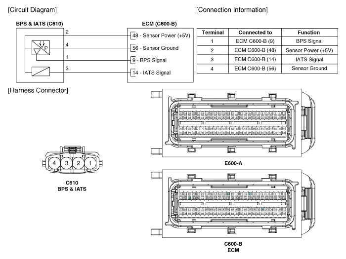
Specification Pressure [kPa (kgf/cm², psi)]Output Voltage (V)10.0 (0.01, 0.15)0.5055.0 (0.56, 7.98)2.21115.0 (1.17, 16.9)4.50
Inspection 1. Connect the GDS on the Data Link Connector (DLC). 2. Measure the output voltage of the BPS at idle and IG ON. Specification: Refer to "Specification" Removal 1.
Other information:
Kia Cadenza YG 2016-2021 Service Manual: Schematic Diagrams
Circuit Diagram SVM System Input/Output 1. Camera input ItemSpecificationLens angle of view190 degreesAngle of viewHorizontal186 degreesVertical135 degreesFunctionProvides the original image of the wide angle image (no additional function)Application locationSame camera applied to the front, rear, left and right 2.
Kia Cadenza YG 2016-2021 Service Manual: Repair procedures
Refrigerant System Service Basics Refrigerant Recovery Use only service equipment that is U.L-listed and is certified to meet the requirements of SAE J2210 to remove HFC-134a(R-134a) from the air conditioning system. – Air conditioning refrigerant or lubricant vapor can irritate your eyes, nose, or th
Categories
- Manuals Home
- Kia Cadenza Owners Manual
- Kia Cadenza Service Manual
- Restraint
- Timing Chain Repair procedures
- Specifications
- New on site
- Most important about car
