
Kia Cadenza YG: Brake System / Brake Pedal Components and Components Location
Kia Cadenza YG 2016-2021 Service Manual / Brake System / Brake System / Brake Pedal Components and Components Location
| Components |
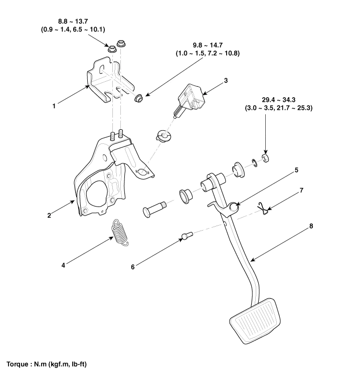
| 1. Cowl bracket 2. Brake pedal member assembly 3. Stop lamp switch 4. Return spring | 5. Brake pedal stopper 6. Clevis pin 7. Snap pin 8. Brake pedal |
Removal 1. Disconnect the brake fiuid level switch connector, and remove the reservoir cap. 2. Remove the brake fluid from the master cylinder reservior with a syringe.
Removal 1. Remove the crash pad lower panel. (Refer to the Body group- crash pad). 2. Remove the shower duct (A). 3. Disconnect the stop lamp switch connector (A).
Categories
- Manuals Home
- Kia Cadenza Owners Manual
- Kia Cadenza Service Manual
- Engine Control / Fuel System
- Components and Components Location
- Battery Troubleshooting
- New on site
- Most important about car

Copyright © 2026 www.kcadenzavg.com - 0.021