Kia Cadenza YG: Engine Control System / Camshaft Position Sensor (CMPS) Repair procedures
Kia Cadenza YG 2016-2021 Service Manual / Engine Control / Fuel System / Engine Control System / Camshaft Position Sensor (CMPS) Repair procedures
| Inspection |
| 1. |
Check the signal waveform of the CMPS and CKPS using the GDS.
|
| Removal |
|

| 1. |
Turn the ignition switch OFF and disconnect the battery negative (-) cable. |
| 2. |
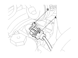
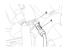
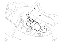
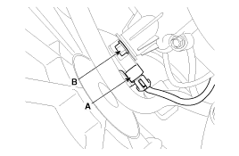
Disconnect the camshaft position sensor connector (A). |
| 3. |
Remove the installation bolt (B), and then vertically remove the sensor from the cylinder head.
[Bank 1/Intake]
[Bank 1/Exhaust]
[Bank 2/Intake]
[Bank 2/Exhaust]
|
| Installation |
|

|
|
|
| 1. |
Install in the reverse order of removal.
|
Circuit Diagram
Description Knocking is a phenomenon characterized by undesirable vibration and noise and can cause engine damage. The two Knock Sensor (KS) are installed inside the V-valley of the cylinder block and senses engine knocking.
Other information:
Kia Cadenza YG 2016-2021 Service Manual: Special Service Tools
S
Kia Cadenza YG 2016-2021 Service Manual: Cluster ionizer Description and Operation
Description 1. The function of cluster ion generator is cleaning air by sterilizing and dissolving of air conditioner. 2. The function of cluster ion generator is controlling mold caused by stench of air conditioner and external inflow of air.
Categories
- Manuals Home
- Kia Cadenza Owners Manual
- Kia Cadenza Service Manual
- Specifications
- Alternator Schematic Diagrams
- Suspension System
- New on site
- Most important about car

Copyright © 2026 www.kcadenzavg.com - 0.0215