Kia Cadenza YG: Auto Lighting Control System / Components and Components Location
Kia Cadenza YG 2016-2021 Service Manual / Body Electrical System / Auto Lighting Control System / Components and Components Location
| Component Location |
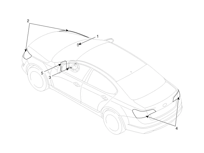
| 1. Auto light sensor 2. Head lamps 3. Lighting switch (Auto) | 4. Tail lamps 5. IPM (Intelligent intergrated Platform Module) |
Specifications ItemsSpecificationsRated voltageDC +5VLoadMax. 1mA (When head lamp lighting)IlluminationsTail lampON : 0.52 ± 0.03 (V)OFF : 1.58 ± 0.
Circuit Diagram
Other information:
Kia Cadenza YG 2016-2021 Service Manual: Repair procedures
Teaching Procedures 1. Key Teaching Procedure Key teaching must be done after replacing a defective PCM(ECM) or when providing additional keys to the vehicle owner. The procedure starts with an PCM(ECM) request for vehicle specific data (PIN code: 6digits) from the tester.
Kia Cadenza YG 2016-2021 Service Manual: Lane Departure Warning System (LDWS) Unit Repair procedures
Removal 1. Disconnect the negative (-) battery terminal. 2. Remove the LDWS unit cover (A). 3. Remove the LDWS unit connector (A). 4. Remove the LDWS unit after widening the mounting clips. Installation 1. Install the LDWS unit. 2.
Categories
- Manuals Home
- Kia Cadenza Owners Manual
- Kia Cadenza Service Manual
- Schematic Diagrams
- Transaxle Control Module (TCM) Repair procedures
- Automatic Transaxle System
- New on site
- Most important about car

Copyright © 2026 www.kcadenzavg.com - 0.0296