Kia Cadenza YG: Auto Lighting Control System / Schematic Diagrams
| Circuit Diagram |
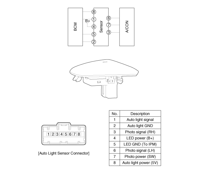
Component Location 1. Auto light sensor2. Head lamps3. Lighting switch (Auto)4. Tail lamps5. IPM (Intelligent intergrated Platform Module)
Inspection Lighting Switch Inspection With the multi function switch in each position, make sure that continuity exists between the terminals below.
Other information:
Kia Cadenza YG 2016-2021 Service Manual: Heater Unit Components and Components Location
Component Location Components 1. Heater Case (LH)2. Separator3. Evaporator Core4. Shower Duct (LH)5. Heater Core Cover6. Heater Core7. Mode Actuator8. Mode Cam9. Temp Actuator (Drive)10. Vent Door Arm11. Floor Door Arm 1. Heater Case (RH)2.
Kia Cadenza YG 2016-2021 Service Manual: Power Mosfet Repair procedures
Inspection 1. Ignition "ON" 2. Manually operate the control switch and measure the voltage of blower motor. 3. Select the control switch to raise voltage until high speed. Specification FanMotor VoltageManualFirst speed3.8 ±0.5VSecond speed5.
Categories
- Manuals Home
- Kia Cadenza Owners Manual
- Kia Cadenza Service Manual
- Alternator Schematic Diagrams
- Restraint
- Engine Mechanical System
- New on site
- Most important about car
