
Kia Cadenza YG: Auto Lighting Control System / Components and Components Location
Kia Cadenza YG 2016-2021 Service Manual / Body Electrical System / Auto Lighting Control System / Components and Components Location
| Component Location |
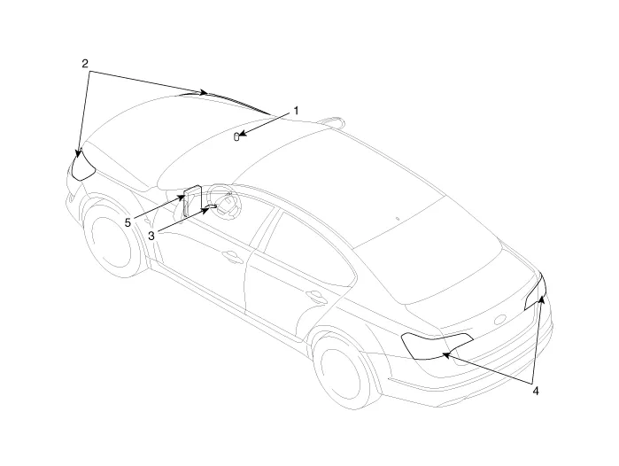
| 1. Auto light sensor 2. Head lamps 3. Lighting switch (Auto) | 4. Tail lamps 5. IPM (Intelligent intergrated Platform Module) |
Specifications ItemsSpecificationsRated voltageDC +5VLoadMax. 1mA (When head lamp lighting)IlluminationsTail lampON : 0.52 ± 0.03 (V)OFF : 1.58 ± 0.
Circuit Diagram
Other information:
Kia Cadenza YG 2016-2021 Service Manual: Auto Head lamp leveling Unit Repair procedures
Removal Height Sensor 1. Remove the height sensor connector (A). 2. Loosen the mounting bolts(Body: 2EA, chassis: 1EA) from height sensor bracket. Tightening torque : 3 ~ 5N.m (30 ~ 50kgf.m, 2.21 ~ 3.68lb-ft) 3. Remove the height sensor.
Kia Cadenza YG 2016-2021 Service Manual: Specifications
S
Categories
- Manuals Home
- Kia Cadenza Owners Manual
- Kia Cadenza Service Manual
- Battery Troubleshooting
- Body (Interior and Exterior)
- Components and Components Location
- New on site
- Most important about car

Copyright © 2026 www.kcadenzavg.com - 0.0263