Kia Cadenza YG: Engine Control System / CVVT Oil Temperature Sensor (OTS) Schematic Diagrams
Kia Cadenza YG 2016-2021 Service Manual / Engine Control / Fuel System / Engine Control System / CVVT Oil Temperature Sensor (OTS) Schematic Diagrams
| Circuit Diagram |
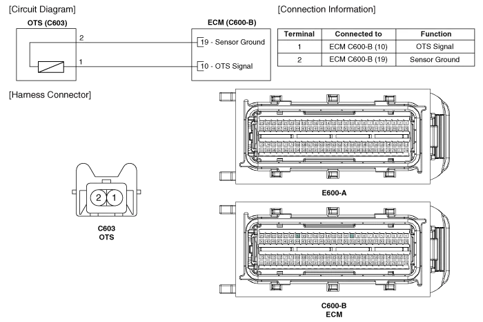
Specification TemperatureResistance (kΩ)°C°F-40-4052.15-20-416.520326.020682.45401041.11601400.54801760.29
Inspection 1. Turn the ignition switch OFF. 2. Disconnect the OTS connector. 3. Remove the OTS. (Refer to "Removal") 4. After immersing the thermistor of the sensor into engine coolant, measure resistance between the OTS terminals 1 and 2.
Other information:
Kia Cadenza YG 2016-2021 Service Manual: Compressor Components and Components Location
C
Kia Cadenza YG 2016-2021 Service Manual: Auto defoging actuator Repair procedures
Inspection 1. Ignition "OFF”. 2. Disconnect the connector of auto defog control actuator. 3. Verify that the auto defog control actuator operates to the defrost ON mode when connecting 12V to the terminal 3 and grounding terminal 7. 4.
Categories
- Manuals Home
- Kia Cadenza Owners Manual
- Kia Cadenza Service Manual
- Body Electrical System
- Body (Interior and Exterior)
- Schematic Diagrams
- New on site
- Most important about car

Copyright © 2026 www.kcadenzavg.com - 0.0194