Kia Cadenza YG: Engine And Transmission Assembly / Engine Mounting Repair procedures
| Removal and Installation |
| 1. |
Disconnect the battery negative terminal. |
| 2. |
Remove the engine room under cover.
(Refer to Engine And Transaxle Assembly – “Engine Room Under Cover”) |
| 3. |
Install the jack to the edge of the upper oil pan to support the engine.
|


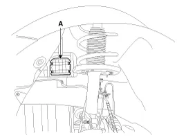
| 4. |
Remove the engine mounting support bracket (A).
|
| 5. |
Remove the engine mounting bracket (B).
|

| 6. |
Install in the reverse order of removal. |
| 1. |
Remove the engine room under cover.
(Refer to Engine And Transaxle Assembly - “Engine Room Under Cover”) |
| 2. |
Remove the roll rod bracket (A).
|

| 3. |
Install in the reverse order of removal. |
| 1. |
Remove the air cleaner assembly.
(Refer to Intake and Exhaust System - "Air Cleaner") |
| 2. |
Remove the battery and battery tray.
(Refer to Engine Electrical System - "Battery") |
| 3. |
Remove the engine control module (ECM).
(Refer to Engine Control/Fuel System - “Engine Control Module (ECM)”) |
| 4. |
Remove the engine room under cover.
(Refer to Engine And Transaxle Assembly - “Engine Room Under Cover”) |
| 5. |
Install the jack to the edge of transaxle. |
| 6. |
Remove the transaxle mounting bracket.
|

| 7. |
Install in the reverse order of removal. |
Components 1. Transaxle mounting bracket2. Roll rod bracket3. Sub frame4. Engine mounting bracket5. Engine mounting support bracket
Removal • Use fender covers to avoid damaging painted surfaces. • To avoid damage, unplug the wiring connectors carefully while holding the connector portion.
Other information:
Kia Cadenza YG 2016-2021 Service Manual: Start/Stop Button Repair procedures
Removal 1. Disconnect the negative (-) battery terminal. 2. Using a screw driver or remover, remove the center fascia lower panel (A). 3. Remove the in-car hose (A) and disconnect the connectors (B) from the heater & A/C control unit. 4.
Kia Cadenza YG 2016-2021 Service Manual: Compressor Repair procedures
Removal 1. If the compressor is marginally operable, run the engine at idle speed, and let the air conditioning work for a few minutes, then shut the engine off. 2. Disconnect the negative cable from the battery. 3. Recover the refrigerant with a recovery/charging station.
Categories
- Manuals Home
- Kia Cadenza Owners Manual
- Kia Cadenza Service Manual
- Battery Troubleshooting
- Body Electrical System
- General Information
- New on site
- Most important about car
