Kia Cadenza YG: Engine And Transmission Assembly / Engine And Transmission Assembly Repair procedures
Kia Cadenza YG 2016-2021 Service Manual / Engine Mechanical System / Engine And Transmission Assembly / Engine And Transmission Assembly Repair procedures
| Removal |
|

|

| 1. |
Disconnect the battery negative terminal. |
| 2. |
Remove the engine cover. |
| 3. |
Remove the air cleaner assembly.
(Refer to Intake and Exhaust System - "Air cleaner") |
| 4. |
Remove the battery and battery tray.
(Refer to Engine Electrical System - "Battery") |
| 5. |
Remove the engine room under cover.
(Refer to Engine And Transaxle Assembly - “Engine Room Under Cover”) |
| 6. |
Drain the coolant.
(Refer to Cooling System - "Coolant") |
| 7. |
Remove the radiator upper hose (A) and lower hose (B).
|


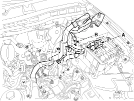
| 8. |
Disconnect the (+) cable (A) from the junction box. |
| 9. |
Disconnect the connectors (B), and then remove the ECM (C).
|

| 10. |
Disconnect the front connector (B), and then remove the wiring protector (A).
|

| 11. |
Disconnect the junction box connector (A) and the ground bolts (B) and then remove the engine wirings from the engine room.
|
| 12. |
Remove the transaxle wire harness connectors and control cable from the transaxle.
(Refer to Automatic transaxle System - "Automatic transaxle") |
| 13. |
Disconnect the ATF cooler hose.
(Refer to Automatic Transaxle System - "Automatic Transaxle") |
| 14. |
Disconnect the brake booster vacuum hose (A), the PSCV hose (B) and the fuel hose (C).
|

| 15. |
Disconnect the heater hoses (A).
|


| 16. |
Recover the refrigerant and then remove the high pressure pipe and low pressure pipe.
(Refer to Heating, Ventilation, Air Conditioning - "Compressor") |
| 17. |
Remove the front muffler.
(Refer to Intake And Exhaust System - "Muffler") |
| 18. |
Remove the roll rod bracket (A).
|

| 19. |
Remove the sub frame.
(Refer to Suspension System - "Sub Frame") |
| 20. |
Disconnect the ground cable (A), and then remove the engine mounting bracket (B).
|

| 21. |
Disconnect the transaxle ground line (A).
|

| 22. |
Remove the service cover (A).
|

| 23. |
Remove the transaxle mounting bolts (A).
|

| 24. |
Remove the engine and transaxle assembly by lifting vehicle.
|

| Installation |
Install in the reverse order of removal.
Perform the following :
| • |
Adjust a shift cable. |
| • |
Refill engine with engine oil. |
| • |
Refill a transaxle with fluid. |
| • |
Refill power steering fluid. |
| • |
Refill a radiator and a reservoir tank with engine coolant. |
| • |
Place a heater control knob on "HOT" position. |
| • |
Clean battery posts and cable terminals and assemble. |
| • |
Inspect for fuel leakage. |
| – |
After assemble the fuel line, turn on the ignition switch (do
not operate the starter) so that the fuel pump runs for approximately
two seconds and fuel line pressurizes. |
| – |
Repeat this operation two or three times, then check for fuel leakage at any point in the fuel line. |
| • |
Bleed air from the cooling system. |
| – |
Start engine and let it run until it warms up. (until the radiator fan operates 3 or 4 times.) |
| – |
Turn Off the engine and let it cool down. Check the level in
the radiator, add coolant if needed. This will allow trapped air to be
removed from the cooling system. |
| – |
Put radiator cap on tightly, then run the engine again and check for leaks. |
Removal and Installation Engine Mounting Bracket 1. Disconnect the battery negative terminal. 2. Remove the engine room under cover. (Refer to Engine And Transaxle Assembly – “Engine Room Under Cover”) 3.
Other information:
Kia Cadenza YG 2016-2021 Service Manual: Description and Operation
Description Adaptive Front-lighting System (AFLS) AFLS(Adaptive Front-lighting System)is a headlamp orientation control system that takes into account both steering angle and vehicle speed to orient the headlamps to an angle that provides better nighttime visibility.
Kia Cadenza YG 2016-2021 Service Manual: Ambient Sensor Repair procedures
Inspection 1. Ignition "OFF" 2. Disconnect ambient temperature sensor. 3. Check the resistance of ambient temperature sensor between terminals 1 and 2 whether it is changed by changing of the ambient temperature. 1. Sensor Ground2.
Categories
- Manuals Home
- Kia Cadenza Owners Manual
- Kia Cadenza Service Manual
- Brake System
- Body (Interior and Exterior)
- Emission Control System
- New on site
- Most important about car

Copyright © 2026 www.kcadenzavg.com - 0.0251