Kia Cadenza YG: ESC(Electronic Stability Control) System / ESC Control Module Components and Components Location
| Components (1) |
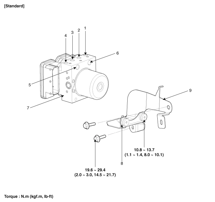
| 1. Front - left tube 2. Rear - right tube 3. Rear - left tube 4. Front - right tube 5. MC2 | 6. MC1 7. ESC control module (HECU) 8. Damper 9. Bracket |
| Components (2) |
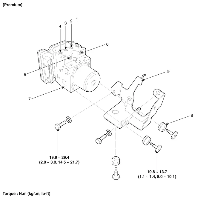
| 1. Front - left tube 2. Rear - right tube 3. Rear - left tube 4. Front - right tube 5. MC2 | 6. MC1 7. ESC control module (HECU) 8. Damper 9. Bracket |
Operation The EBD system (Electronic Brake force Distribution) as a sub-system of the ABS system is to control the maximum braking effectiveness by the rear wheels.
Removal 1. Turn the ignition switch OFF. 2. Remove the air duct (B) and air cleaner assembly (A). 3. Remove the connector and then arrange the wiring harness (A).
Other information:
Kia Cadenza YG 2016-2021 Service Manual: Repair procedures
Diagnosis With GDS 1. BSD system defects can be quickly diagnosed with the GDS. GDS operates actuator quickly to monitor, input/output value and self diagnosis. 2. Connect the cable of GDS to the data link connector in driver side crash pad lower panel, turn the power on GDS.
Kia Cadenza YG 2016-2021 Service Manual: Photo Sensor Description and Operation
Description 1. The photo sensor is located at the center of defrost nozzle. 2. The photo sensor contains a photovoltaic (sensitive to sunlight) diode. The solar radiation received by its light receiving portion, generates an electromotive force in proportion to the amount of radiation received which is transferred to the automatic tem
Categories
- Manuals Home
- Kia Cadenza Owners Manual
- Kia Cadenza Service Manual
- Engine Control / Fuel System
- General Information
- Rail Pressure Sensor (RPS) Schematic Diagrams
- New on site
- Most important about car
