Kia Cadenza YG: ESC(Electronic Stability Control) System / ESC Control Module Repair procedures
| Removal |
| 1. |
Turn the ignition switch OFF. |
| 2. |
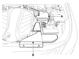
Remove the air duct (B) and air cleaner assembly (A).
|
| 3. |
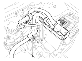
Remove the connector and then arrange the wiring harness (A).
|
| 4. |
Remove the brake fluid from the master cylinder reservoir with a syringe.
|

| 5. |
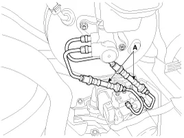
Loosen the flare nuts and then remove the brake tube (A).
|
| 6. |
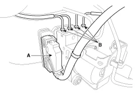
Pull up the lock of the HECU connector (A) and then disconnect the connector.
|
| 7. |
Disconnect the brake tubes from the HECU by unlocking the nuts (B) counterclockwise with a spanner.
|
| 8. |
Loosen the HECU bracket bolts (A) and then remove HECU and bracket.
|
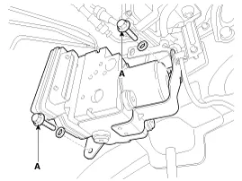
| 9. |
Remove the bolts and then remove the bracket from HECU.
|
| Installation |
| 1. |
Installation is the reverse of removal. |
| 2. |
Tighten the HECU mounting bolts and nuts to the specified torque. |
| 3. |
After installation, bleed the brake system.(Refer to ABS bleeding) |
| 4. |
When you have replaced the HECU always perform variant coding. |
| 1. |
Connect the GDS to the data link connector. |
| 2. |
Turn the ignition "ON". |
| 3. |
Select vehicle name and system. |
| 4. |
Select the variant coding.
|
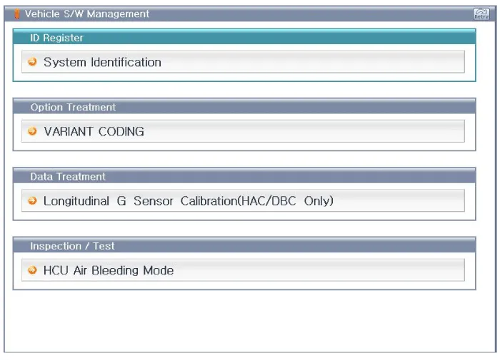
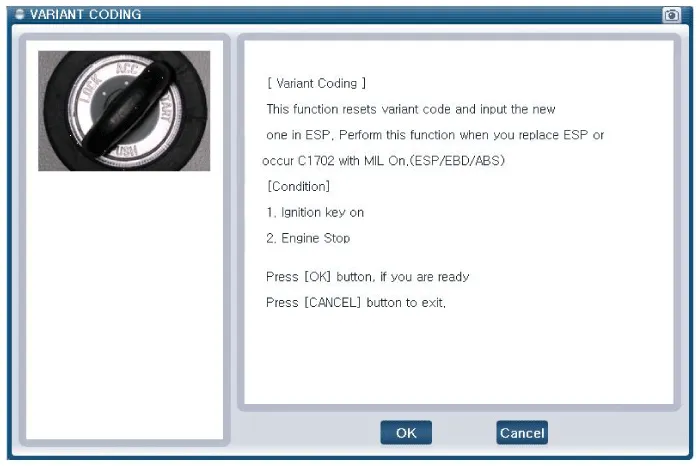
| 5. |
Perform variant coding according to the instructions on the screen.
|

| 6. |
Ignition "OFF" and then ignition "ON". |
| 7. |
The variant coding is completed. |
Components (1) 1. Front - left tube2. Rear - right tube3. Rear - left tube4. Front - right tube5. MC26. MC17. ESC control module (HECU)8. Damper9.
Components 1. Front wheel speed sensor2. Front wheel speed sensor connector
Other information:
Kia Cadenza YG 2016-2021 Service Manual: Blind Spot Detection Radar Calibration Description and Operation
Description To sense the cars exactly in the next lane with the radar, the direction of the sensor and the direction of the vehicle have to align. This is BSD unit alignment. If this alignment is not performed as below illustration, the degradation of detection performance and the cause of false alarms.
Kia Cadenza YG 2016-2021 Service Manual: Evaporator unit Repair procedures
Inspection 1. Ignition "OFF". 2. Disconnect evaporator temperature sensor. 3. Using the multi-tester, Measure resistance between terminal "1" and "2" of evaporator temperature sensor. Specification Evaporator coretemperature [°C(°F)]Resistance[KΩ]Voltage[V]-20(-4)70.
Categories
- Manuals Home
- Kia Cadenza Owners Manual
- Kia Cadenza Service Manual
- Timing Chain Repair procedures
- Engine Mechanical System
- Specifications
- New on site
- Most important about car
