Kia Cadenza YG: Engine Control System / ETC (Electronic Throttle Control) System Schematic Diagrams
| Circuit Diagram |
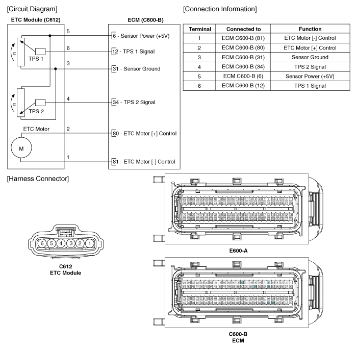
Specification [Throttle Position Sensor (TPS)] Throttle angle(°)Output Voltage (V) [Ref=5V]TPS1TPS200.54.5100.964.05201.413.59301.873.14402.322.
Inspection Throttle Position Sensor (TPS) 1. Connect the GDS on the Data Link Connector (DLC). 2. Start the engine and measure the output voltage of TPS 1 and 2 at C.
Other information:
Kia Cadenza YG 2016-2021 Service Manual: Adaptive Front Lighting System Repair procedures
Removal 1. Disconnect the negative (-) battery terminal. 2. Using a screwdriver or remover, remove the crash pad side cover (A). [RH] 3. Disconnect the stopper (B) from the glove box (A). 4. Disconnect the air damper (A) from the glove box (B).
Kia Cadenza YG 2016-2021 Service Manual: Immobilizer Control Unit Repair procedures
Removal 1. Disconnect the negative (-) battery terminal. 2. Remove the crash pad lower panel. (Refer to Body - "Crash Pad") 3. Disconnect the 5P connector of the SMARTRA unit and then remove the SMARTRA unit (A) after loosening the bolt. Installation 1.
Categories
- Manuals Home
- Kia Cadenza Owners Manual
- Kia Cadenza Service Manual
- Mode Control Actuator Repair procedures
- Transaxle Control Module (TCM) Repair procedures
- Front Hub - Axle Repair procedures
- New on site
- Most important about car
