Kia Cadenza YG: Engine Control System / ETC (Electronic Throttle Control) System Specifications
| Specification |
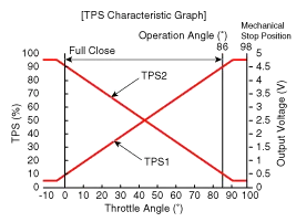
| Throttle angle(°) | Output Voltage (V) [Ref=5V] | |
| TPS1 | TPS2 | |
| 0 | 0.5 | 4.5 |
| 10 | 0.96 | 4.05 |
| 20 | 1.41 | 3.59 |
| 30 | 1.87 | 3.14 |
| 40 | 2.32 | 2.68 |
| 50 | 2.78 | 2.23 |
| 60 | 3.23 | 1.77 |
| 70 | 3.69 | 1.32 |
| 80 | 4.14 | 0.86 |
| 90 | 4.6 | 0.41 |
| 98 | 4.65 | 0.35 |
| C.T (0) | 0.5 | 4.5 |
| W.O.T (86) | 4.41 | 0.59 |
| Item | Specification |
| Coil Resistance (Ω) | 0.3 ~100 [20°C(68°F)] |
Fail-Safe Mode ItemFail-SafeETC MotorThrottle valve stuck at 7°TPSTPS 1 faultECM looks at TPS2TPS 2 faultECM looks at TPS1TPS 1,2 faultThrottle valve stuck at 7°APSAPS 1 faultECM looks at APS 2APS 2 faultECM looks at APS 1APS 1,2 faultEngine idle state When throttle value is stuck at 7°, engine speed is limited at below 1,500rpm and vehicle speed at maximum 40 ~ 50 km/h (25 ~ 31 mph)
Circuit Diagram
Other information:
Kia Cadenza YG 2016-2021 Service Manual: Height Sensor Repair procedures
Removal Height Sensor 1. Disconnect the negative (-) battery terminal. 2. Remove the height sensor linkage (A) installed on the front axle and rear axle. [Front] [Rear] Installation Height Sensor 1. Install the height sensor assembly after connecting the connector.
Kia Cadenza YG 2016-2021 Service Manual: Photo Sensor Description and Operation
Description 1. The photo sensor is located at the center of defrost nozzle. 2. The photo sensor contains a photovoltaic (sensitive to sunlight) diode. The solar radiation received by its light receiving portion, generates an electromotive force in proportion to the amount of radiation received which is transferred to the automatic tem
Categories
- Manuals Home
- Kia Cadenza Owners Manual
- Kia Cadenza Service Manual
- Rail Pressure Sensor (RPS) Schematic Diagrams
- Body Electrical System
- Schematic Diagrams
- New on site
- Most important about car
