Kia Cadenza YG: Engine Control System / ETC (Electronic Throttle Control) System Schematic Diagrams
Kia Cadenza YG 2016-2021 Service Manual / Engine Control / Fuel System / Engine Control System / ETC (Electronic Throttle Control) System Schematic Diagrams
| Circuit Diagram |
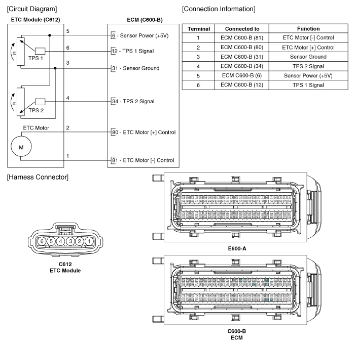
Specification [Throttle Position Sensor (TPS)] Throttle angle(°)Output Voltage (V) [Ref=5V]TPS1TPS200.54.5100.964.05201.413.59301.873.14402.322.
Inspection Throttle Position Sensor (TPS) 1. Connect the GDS on the Data Link Connector (DLC). 2. Start the engine and measure the output voltage of TPS 1 and 2 at C.
Other information:
Kia Cadenza YG 2016-2021 Service Manual: Components and Components Location
C
Kia Cadenza YG 2016-2021 Service Manual: Auto defoging sensor Repair procedures
Inspection 1. Press the OFF switch more then 4 times within 2 seconds while pressing the MODE switch. DisplayFail description00Normal23Auto defog sensor OPEN24Auto defog sensor SHORT43Defog door potentiometer OPEN/SHORT44Defog door potentiometer * Diagnostic procedure refer to DTC code.
Categories
- Manuals Home
- Kia Cadenza Owners Manual
- Kia Cadenza Service Manual
- Transaxle Control Module (TCM) Repair procedures
- Restraint
- Engine Mechanical System
- New on site
- Most important about car

Copyright © 2026 www.kcadenzavg.com - 0.0216