Kia Cadenza YG: Driveshaft Assembly / Front Driveshaft Repair procedures
| Replacement |
| 1. |
Loosen the wheel nuts slightly.
Raise the vehicle, and make sure it is securely supported. |
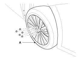
| 2. |
Remove the front wheel and tire (A) from front hub.
|

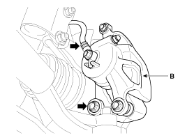
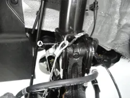
| 3. |
Remove the brake caliper mounting bolts , and then place the brake caliper assembly (B) with wire.
|
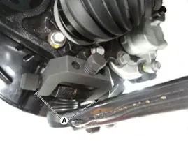
| 4. |
Remove the tie rod end ball joint (A) from the knuckle.
|
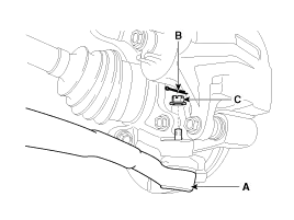
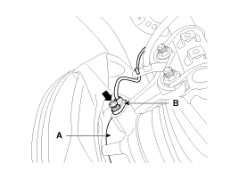
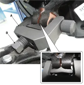
| 5. |
Loosen the mount bolt and then remove the wheel speed sensor (B) from knuckle (A).
|
| 6. |
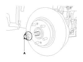
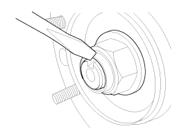
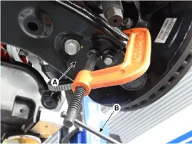
Remove driveshaft coking nut (A) from the front hub under applying the break.
|
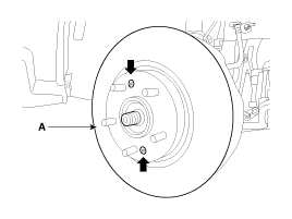
| 7. |
Loosen the front brake disc mount screw and then remove the front brake disc (A).
|
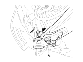
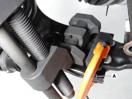
| 8. |
Remove the lower arm (A) from the knuckle.
|
| 9. |
Remove the front lower arm from the front knuckle using the SST (0K545-A9100).
|


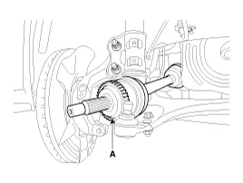
| 10. |
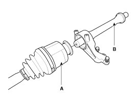
Disconnect the driveshaft (A) from the front hub assembly.
|
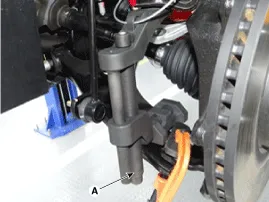
| 11. |
Remove the driveshaft cover (A).
|

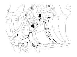
| 12. |
Loosen the mounting bolts and then remove the inner shaft (A) & driveshaft assembly (B).
|
| 13. |
Disconnect the driveshaft (A) from inner shaft (B).
|
| 14. |
Install in the reverse order of removal.
|
| Inspection |
| 1. |
Check the driveshaft boots for damage and deterioration. |
| 2. |
Check the driveshaft spline for wear or damage. |
| 3. |
Check that there is no water or foreign material in the joint. |
| 4. |
Check the spider assembly for roller rotation, wear or corrosion. |
| 5. |
Check the groove inside the joint case for wear or corrosion. |
| 6. |
Check the dynamic damper for damage or cracks. |
| Disassembly |
|
| 1. |
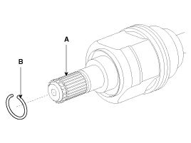
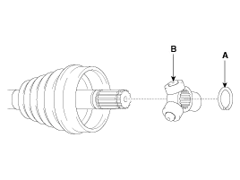
Remove the circlip (B) from the driveshaft spline (A).
|
| 2. |
Remove both boot bands from the transaxle side joint (UTJ) case.
|
| 3. |
Pull out the boot from transaxle side joint case (B). |
| 4. |
While dividing joint (UTJ) boot (A) of the transaxle side, wipe the grease in UTJ case (B) and collect them respectively.
|
| 5. |
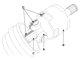
Remove the snap ring (A) and spider roller assembly (B) from the shaft.
|
| 6. |
Clean the spider assembly. |
| 7. |
Remove the boot (A) of the transaxle side joint (UTJ).
|
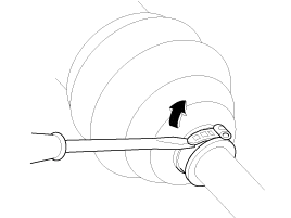
| 8. |
Using a pillar or flat-tipped (-) screwdriver, remove the both side of clamp (B) of the dynamic damper (A).
|
| 9. |
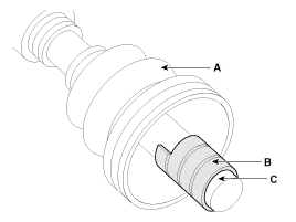
Fix the driveshaft (A) with a vice (B) as illustrated.
|
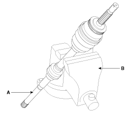
| 10. |
Apply soap powder on the shaft to prevent being damaged
between the shaft spline and the dynamic damper when the dynamic damper
is removed. |
| 11. |
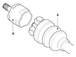
Saperate the dynamic damper (A) from the shaft (B) carefully.
|

| Reassembly |
| 1. |
Wrap tape around the driveshaft spline (UTJ) to prevent damage to the boots. |
| 2. |
Apply grease to the joint boot on the side of the wheel and install the boot. |
| 3. |
Install the clamp. |
| 4. |
To install the dynamic damper (A), keep the shaft in a straight line and assemble the dynamic damper with the bands (B).
|
| 5. |
Assemble the transaxle side joint boot and bands. |
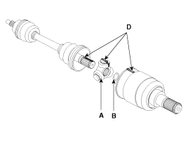
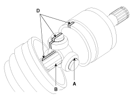
| 6. |
Using the alignment marks (D) made during disassembly as a
guide, install the spider assembly (A) and snap ring (B) on the
driveshaft splines (C).
|
| 7. |
Add specified grease to the joint boot as much as it was wiped away at inspection. |
| 8. |
Install the both boot band. |
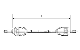
| 9. |
To control the air in the UTJ boot, keep the specified distance between the boot bands when they are tightened.
| ||||||||
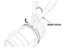
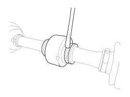
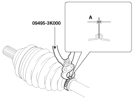
| 10. |
Using the SST (09495-3K000), secure the UTJ boot bands.
|
Component Location 1. Driveshaft(LH)2. Circlip3. Inner shaft bearing bracket assembly4. Circlip5. Driveshaft(RH)6. Components 1. BJ Assembly2.
Other information:
Kia Cadenza YG 2016-2021 Service Manual: Description and Operation
Description Surround View Monitoring System (SVM) is the system that allows video monitoring of 360 degrees around the vehicle. The system includes 4 ultra optical camera mounted around the vehicle (front, both sides, rear). The video from these cameras are applied with distortion compensation, time point conversion, and video merging
Kia Cadenza YG 2016-2021 Service Manual: Blower Unit Repair procedures
Replacement 1. Disconnect the negative (-) battery terminal. 2. Remove the heater and blower unit.(Refer to HA group – heater unit). 3. Remove the blower unit (A) from the heater unit after loosening a mounting bolt and 3 screws. Make sure that there is no air leaking out of the blower and duct joints.
Categories
- Manuals Home
- Kia Cadenza Owners Manual
- Kia Cadenza Service Manual
- Battery Troubleshooting
- Automatic Transaxle System
- Steering System
- New on site
- Most important about car
