
Kia Cadenza YG: Heater / Heater Unit Repair procedures
| Replacement |
| 1. |
Disconnect the negative (-) battery terminal. |
| 2. |
Recover the refrigerant with a recovery/ recycling/ charging station. |
| 3. |
When the engine is cool, drain the engine coolant from the radiator. |
| 4. |
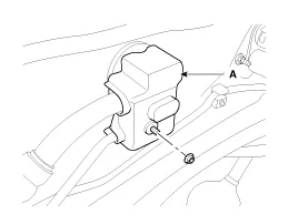
Remove the expansion valve cover (A).
|
| 5. |
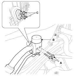
Remove the bolts (A) and the expansion valve (B) from the evaporator core.
Plug or cap the lines immediately after disconnecting them to avoid moisture and dust contamination.
|
| 6. |
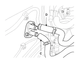
Disconnect the inlet (C) and outlet (D) heater hoses from the heater unit.
|

| 7. |
Remove the floor console assembly.
(Refer to BD group - "Console") |
| 8. |
Remove the steering wheel.
(Refer to SS group - "steering column") |
| 9. |
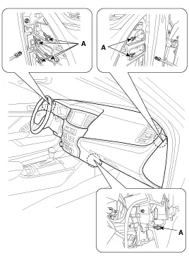
Loosen the cowl cross member mounting bolts(A).
|
| 10. |
Disconnect the right main harness connectors(A).
|
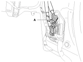
| 11. |
Disconnect the lift junction box connectors(A).
|
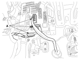
| 12. |
Disconnect the left main connectors (A).
|
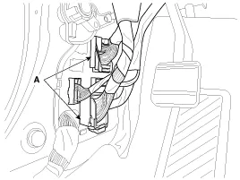
| 13. |
Loosening the heater & blower unit mounting bolts(A) and then remove the heater & blower unit.
|
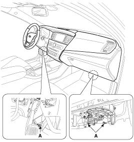
| 14. |
Remove the incar sensor hose(A).
|
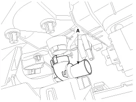
| 15. |
Disconnect the heater & blower unit(A) from crash pad.
|
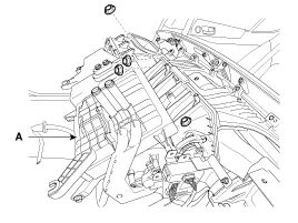
| 16. |
Remove the blower unit from heater unit (A) after loosening 3 screws.
|
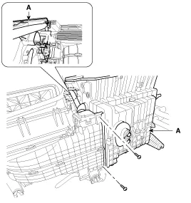
| 17. |
Loosen the mounting screw and then remove the heater core cover(A).
|
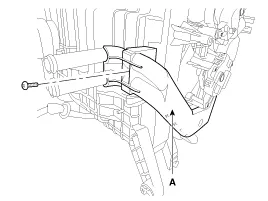
| 18. |
Remove the heater core(A) from heater unit.
|
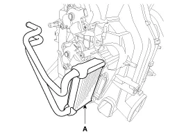
| 19. |
Loosen the heater unit lower case mounting screws and then remove the heater unit lower case (A).
|
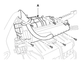
| 20. |
Remove the evaporator core (A).
|
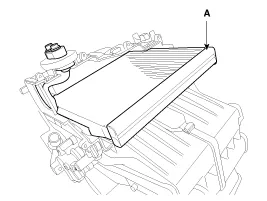
| 21. |
Be careful that the inlet and outlet pipe are not bent during heater core removal, and pull out the heater core. |
| 22. |
Installation is the reverse order of removal. |
| 23. |
Installation is the reverse order of removal, and note these items :
|
Component Location Components 1. Heater Case (LH)2. Separator3. Evaporator Core4. Shower Duct (LH)5. Heater Core Cover6. Heater Core7. Mode Actuator8.
Component Location
Other information:
Kia Cadenza YG 2016-2021 Service Manual: Auto Head lamp leveling Unit Description and Operation
Description According to driving environment and loading state of vehicle, head lamp lighting direction is changed to keep the driver''s visibility range and to protect the driver''s vision from glare, aiming at safety driving. Sensor mounting on the rear center arm drives the actuator mounting on the head lamp since sensing the input
Kia Cadenza YG 2016-2021 Service Manual: Intake Actuator Repair procedures
Inspection 1. Ignition "OFF". 2. Disconnect the intake actuator connector. 3. Verify that the actuator operates to the recirculation position when connecting 12V to the terminal 3 and grounding terminal 7. 4. Verify that the intake actuator operates to the fresh position when connecting in the reverse.
Categories
- Manuals Home
- Kia Cadenza Owners Manual
- Kia Cadenza Service Manual
- Body Control Module (BCM) Description and Operation
- Engine Electrical System
- Schematic Diagrams
- New on site
- Most important about car
