Kia Cadenza YG: IMS (Integrated Memory) / IMS Control Switch Schematic Diagrams
Kia Cadenza YG 2016-2021 Service Manual / Body Electrical System / IMS (Integrated Memory) / IMS Control Switch Schematic Diagrams
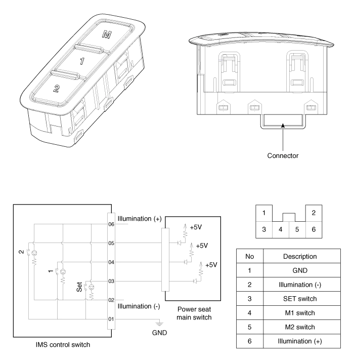
| Circuit diagram |
Removal 1. Remove the negative (-) battery terminal. 2. Remove the driver seat in the car. (Refer to Body - "Front Seat") 3. Remove the IMS module (A) after loosening 3 screws in the bottom of seat.
Inspection 1. Disconnect the IMS control switch connector. 2. With the power IMS control switch in each position, make sure that continuity exists between the terminals below.
Other information:
Kia Cadenza YG 2016-2021 Service Manual: Blind Spot Detection Variant Coding Description and Operation
Description The used radar frequency of BSD is two, "North America region" and "Except North America region". If it replaces BSD unit, BSD unit has to perform the procedure of variant coding. BSD Variant Coding 1. Select the "BSD Variant Coding" procedure in BSD system.
Kia Cadenza YG 2016-2021 Service Manual: Intake Actuator Description and Operation
D
Categories
- Manuals Home
- Kia Cadenza Owners Manual
- Kia Cadenza Service Manual
- Alternator Schematic Diagrams
- Engine Control / Fuel System
- Battery Troubleshooting
- New on site
- Most important about car

Copyright © 2026 www.kcadenzavg.com - 0.0183