Kia Cadenza YG: Indicators And Gauges / Instrument Cluster Components and Components Location
Kia Cadenza YG 2016-2021 Service Manual / Body Electrical System / Indicators And Gauges / Instrument Cluster Components and Components Location
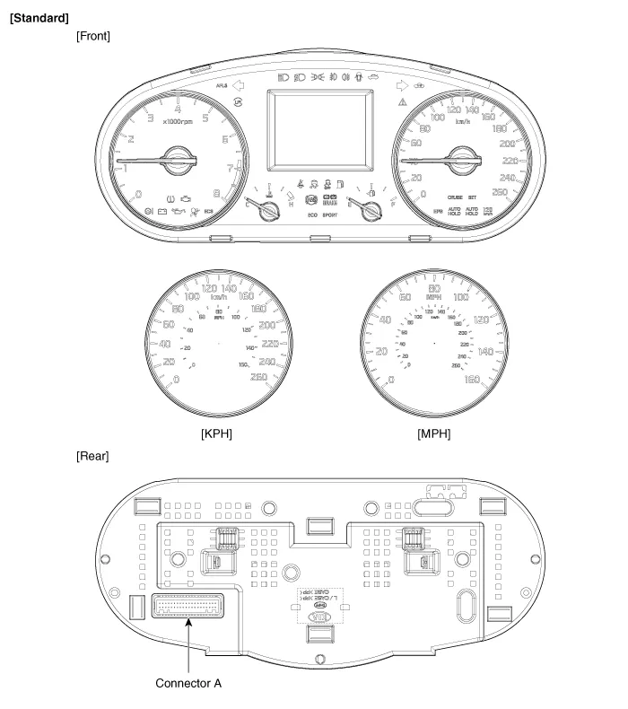
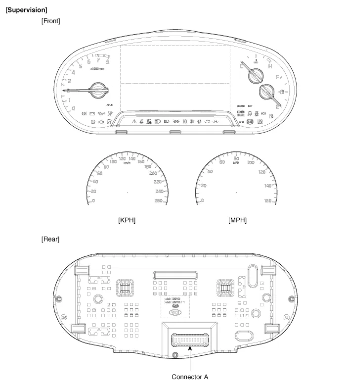
| Components |
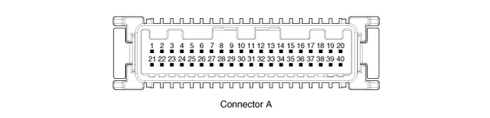
Connector Pin Information
| No. | Description | No. | Description |
| 1 | Air bag (+) | 21 | Aig bag (-) |
| 2 | Trip switch (+) | 22 | Speaker output (+) |
| 3 | Cruise switch (+) | 23 | Speaker output (-) |
| 4 | Rheostat down switch (-) | 24 | Trip switch (-) |
| 5 | Rheostat up switch (-) | 25 | VS 4P output (-) |
| 6 | Oil pressure (-) | 26 | AT R output (+) |
| 7 | Washer indicator (-) | 27 | AT P output (+) |
| 8 | Battery charge (-) | 28 | Detent output (+) |
| 9 | H/SWHL indicator (+) | 29 | Immobilizer (-) |
| 10 | Brake oil switch (-) | 30 | MM CAN high |
| 11 | Active ECO switch (-) | 31 | MM CAN low |
| 12 | Driving mode switch (-) | 32 | C CAN low |
| 13 | AT D output (+) | 33 | C CAN high |
| 14 | Fuel (+) | 34 | AT N output (+) |
| 15 | AT S output (+)(AT) | 35 | Illumniation (-) |
| 16 | Fuel (-) | 36 | P ground |
| 17 | - | 37 | S ground |
| 18 | Glass status signal (-) | 38 | - |
| 19 | - | 39 | IGN 1 (+) |
| 20 | Illumination (+) | 40 | Battery (+) |
Component Location 1. Instrument cluster assembly2. Seat belt switch3. Vehicle speed sensor4. Engine coolant temperature sender5. Oil pressure switch6.
Circuit Diagram
Other information:
Kia Cadenza YG 2016-2021 Service Manual: Description and Operation
Description Surround View Monitoring System (SVM) is the system that allows video monitoring of 360 degrees around the vehicle. The system includes 4 ultra optical camera mounted around the vehicle (front, both sides, rear). The video from these cameras are applied with distortion compensation, time point conversion, and video merging
Kia Cadenza YG 2016-2021 Service Manual: Special Service Tools
S
Categories
- Manuals Home
- Kia Cadenza Owners Manual
- Kia Cadenza Service Manual
- Suspension System
- Emission Control System
- General Information
- New on site
- Most important about car

Copyright © 2026 www.kcadenzavg.com - 0.0177