Kia Cadenza YG: Indicators And Gauges / Instrument Cluster Repair procedures
| Inspection |
| 1. |
Adjust the pressure of the tires to the specified level. |
| 2. |
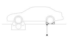
Drive the vehicle onto a speedometer tester. Use wheel chocks (A) as appropriate. |
| 3. |
Check if the speedometer indicator range is within the standard values.
[km/h]
[MPH]
| ||||||||||||||||||||||||||||||||||||||||||||||||||||||||


| 1. |
Connect the GDS to the diagnostic link connector or install a tachometer. |
| 2. |
With the engine started, compare the readings of the tester
with that of the tachometer. Replace the tachometer if the tolerance is
exceeded.
|
| 1. |
Using an ohmmeter, measure the resistance between terminals 1 and 3 of sender connector (A) at each float level.
|
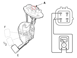
| 2. |
Also check that the resistance changes smoothly when the float is moved from "E" to "F"
[Standard - Gasoline]
[Supervision - Gasoline]
|
| 3. |
If the height resistance is unsatisfied, replace the fuel sender as an assembly.
|
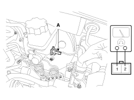
| 1. |
Remove the connector (A) from the switch located at the brake fluid reservoir. |
| 2. |
Verify that continuity exists between switch terminals 1 and 2 while pressing the switch (float) down with a rod.
|
| 1. |
Ignition "ON" |
| 2. |
Release the parking brake. |
| 3. |
Remove the connector from the brake fluid level warning switch. |
| 4. |
Ground the connector at the harness side. |
| 5. |
Verify that the warning lamp lights. |
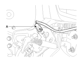
| 1. |
Check that there is continuity between the terminal and switch body with the switch ON (Lever is pulled). |
| 2. |
Check that there is no continuity between the terminal and switch body with the switch OFF (Lever is released).
If continuity is not as specified, replace the switch or inspect its ground connection.
|
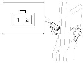
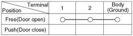
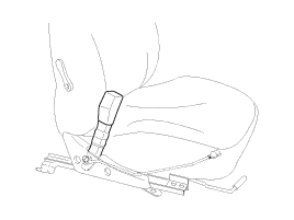
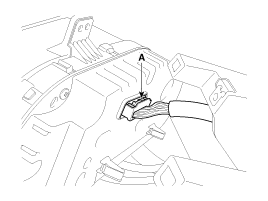
| 1. |
Remove the connector from the switch. |
| 2. |
Check for continuity between terminals.
|
| Seat belt condition | Warning lamp |
| Fastened | OFF |
| Not fastened | ON |
| Removal |
| 1. |
Disconnect the negative (-) battery terminal. |
| 2. |
Tilt the steering column down. |
| 3. |
Remove the cluster facia panel after removing the screws.
(Refer to Body - "Crash Pad") |
| 4. |
Remove the instrument cluster (A) after loosening the screws.
|

| 5. |
Disconnect the cluster connector (A), then remove the cluster.
|
| 1. |
Remove the crash pad lower panel.
(Refer to Body - "Crash Pad") |
| 2. |
Remove the speaker (A) after removing the screws (2EA) and connector.
|

| Installation |
| 1. |
Install the cluster to the cluster housing. |
| 2. |
Install the cluster fascia lower panel. |
| 1. |
Install the speaker after connecting the connector. |
| 2. |
Install the crash pad lower panel. |
Circuit Diagram
Troubleshooting SymptomPossible causeRemedySpeedometer does not operateCluster fuse (10A) blownCheck for short and replace fuseSpeedometer faultyCheck speedometerCAN line faultyCheck the TCUWiring or ground faultyRepair if necessaryTachometer does not operateCluster fuse (10A) blownCheck for short and replace fuseTachometer faultyCheck tachometerCAN line faultyCheck the TCUWiring or ground faultyRepair if necessaryFuel gauge does not operateCluster fuse (10A) blownCheck for short and replace fuseFuel gauge faultyCheck gaugeFuel sender faultyCheck fuel senderWiring or ground faultyRepair if necessaryLow fuel warning lamp does not light upCluster fuse (10A) blownCheck for short and replace fuseFuel level lamp faultyCheck fuel level lampFuel sender faultyCheck fuel senderWiring or ground faultyRepair if necessaryWater temperature gauge does not operateCluster fuse (10A) blownCheck for short and replace fuseWater temperature gauge faultyCheck gaugeWater temperature sender faultyCheck senderCAN line faultyCheck the EMSWiring or ground faultyRepair if necessaryOil pressure warning lamp does not light upCluster fuse (10A) blownCheck for short and replace fuseBulb burned outReplace bulbOil pressure switch faultyCheck switchWiring or ground faultyRepair if necessaryParking brake warning lamp does not light upCluster fuse (10A) blownCheck for short and replace fuseParking brake warning lamp faultyCheck parking brake warning lampBrake fluid level warning switch faultyCheck switchParking brake switch faultyCheck switchWiring or ground faultyRepair if necessaryCAN line faultyCheck the IPMOpen door warning lamp and tailgate warning lamp do not light upMemory fuse (15A) blownCheck for short and replace fuseDoor warning and tailgate warning lamp faultyCheck warning and tailgate warning lampDoor switch faultyCheck switchWiring or ground faultyRepair if necessaryCAN line faultyCheck the IPMSeat belt warning lamp does not light upCluster fuse (10A) blownCheck for short and replace fuseSpeedometer and odometer faultyCheck speedometer and odometerSeat belt switch faultyCheck switchWiring or ground faultyRepair if necessaryCAN line faultyCheck the IPMSpeedometer and odometer does not operateCAN line faultyCheck the ABS ECUSeat belt warning lamp faultyCheck seat belt warning lamp
Other information:
Kia Cadenza YG 2016-2021 Service Manual: Description and Operation
System Overview RPAS (Rear Parking Assist System) is an electronic driving aid that warns the driver to be cautious while parking or in low speed environments. The sensor uses ultrasonic waves to detect objects within proximity of the vehicle.
Kia Cadenza YG 2016-2021 Service Manual: Repair procedures
Diagnosis With GDS 1. BSD system defects can be quickly diagnosed with the GDS. GDS operates actuator quickly to monitor, input/output value and self diagnosis. 2. Connect the cable of GDS to the data link connector in driver side crash pad lower panel, turn the power on GDS.
Categories
- Manuals Home
- Kia Cadenza Owners Manual
- Kia Cadenza Service Manual
- Body (Interior and Exterior)
- Schematic Diagrams
- Specifications
- New on site
- Most important about car
