Kia Cadenza YG: Audio / Audio Unit Repair procedures
| Removal |
|

| 1. |
Disconnect the negative (-) battery terminal. |
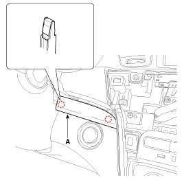
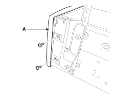
| 2. |
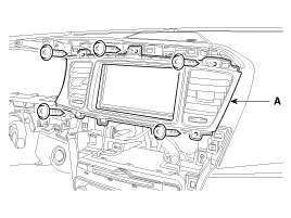
Using the flat driver or remover, remove the center fascia lower panel (A).
|

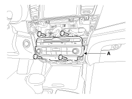
| 3. |
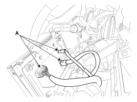
Disconnect the connectors (A) from the center fascia panel.
|
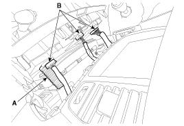
| 4. |
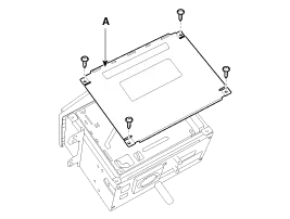
Remove the audio head unit (A) after loosening the mounting screws.
|
| 5. |
Remove the audio head unit connectors and cables.
|

| 1. |
Remove the crash pad center fascia panel.
(Refer to the BE group - "Audio System") |
| 2. |
Using the flat driver or remover, remove the center fascia lower panel (A).
|
| 3. |
Disconnect the connector (B) and incar hose (A).
|
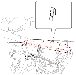
| 4. |
Using the flat driver or remover, remove the crash pad garnish [RH] (A).
|
| 5. |
Using the flat driver or remover, remove the crash pad center garnish (A).
|

| 6. |
Using the flat driver or remover, remove the left crash pad side cover (A).
|

| 7. |
Remove the crash pad garnish [LH] (A) after loosening the mounting screw.
|

| 8. |
Remove the cluster fascia panel (A) after loosening the mounting screws.
|
| 9. |
Remove the center fascia upper panel (A) after loosening the mounting screws.
|
| 10. |
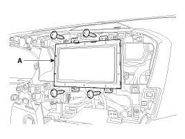
Remove the monitor (A) after loosening the mounting screws.
|
| 11. |
Disconnect the monitor connectors (A).
|
| Installation |
| 1. |
Connect the audio unit connectors and cables. |
| 2. |
Install the audio unit. |
| 3. |
Install the center fascia lower panel. |
| 4. |
Connect the nagative (-) battery terminal.
|
| 1. |
Install the monitor. |
| 2. |
Install the cluster fascia panel, crash pad garnish [LH],
crash pad side cover, crash pad center garnish and crash pad garnish
[RH]. |
| 3. |
Install the center fascia lower panel. |
| 4. |
Connect the negative (-) battery terminal. |
| Disassembly |
|
| 1. |
Remove the top cover (A) from the audio head unit after loosening the mounting screws (4EA).
|
| 2. |
Remove the front cover (A) after loosening the screws.
|
| 3. |
Disconnect the film connector (A) between the unit and the drive.
|

| Reassembly |
| 1. |
Reconnect the film connector between the drive and audio head unit. |
| 2. |
Reassemble the front cover. |
| 3. |
Reassemble the top cover.
|
Components Connector Pin Information Pin No.Connector AConnector BConnector C1Rear left speaker (+)CAN highPower ground2Front left speaker (+)--3Front right speaker (+)--4Rear right speaker (+)Steering wheel remote-5---6-USB D (+)-7-USB/iPod VDDMonitor Rx DP8Illumination (+)AUX right inputMonitor Rx DN9DetentAUX ground-10Rear left speaker (-)MIC (+) (Bluetooth)-11Front left speaker (-)ACC-12Front right speaker (-)Battery (+)R Detect13Rear right speaker (-)CAN low-14---15--Monitor Tx DN16-SpeedMonitor Tx DP17Illumination (-)Remote ground 18Remote antennaUSB D (-)19 iPod/USB ground20AUX Detect21AUX left input22MIC (-) (Bluetooth)23-24Power ground
Inspection 1. Troubleshooting for Speaker (1) Basic inspection of speaker Inspect the sound from speaker after verifying that the speaker mounting screws are removed and the wiring connector is connected to remove any possible vibration transmitted from body trims and surrounding parts.
Other information:
Kia Cadenza YG 2016-2021 Service Manual: Description and Operation
Description Adaptive Front-lighting System (AFLS) AFLS(Adaptive Front-lighting System)is a headlamp orientation control system that takes into account both steering angle and vehicle speed to orient the headlamps to an angle that provides better nighttime visibility.
Kia Cadenza YG 2016-2021 Service Manual: Lane Departure Warning System (LDWS) Unit Repair procedures
Removal 1. Disconnect the negative (-) battery terminal. 2. Remove the LDWS unit cover (A). 3. Remove the LDWS unit connector (A). 4. Remove the LDWS unit after widening the mounting clips. Installation 1. Install the LDWS unit. 2.
Categories
- Manuals Home
- Kia Cadenza Owners Manual
- Kia Cadenza Service Manual
- Body Electrical System
- Specifications
- Schematic Diagrams
- New on site
- Most important about car
