Kia Cadenza YG: Charging System / Battery Repair procedures
Kia Cadenza YG 2016-2021 Service Manual / Engine Electrical System / Charging System / Battery Repair procedures
| Removal |
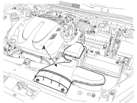
| 1. |
Remove the air duct (A).
|
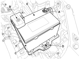
| 2. |
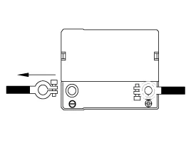
Disconnect the battery (-) terminal (A)and then (+) terminal (B). |
| 3. |
Remove the battery mounting bracket (D) and the insulation pad (C), and then remove the battery (E).
|
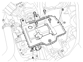
| 4. |
Disconnect the front connector mounting clip (A). |
| 5. |
Remove the battery tray (B) after removing the bolts.
|
| Installation |
| 1. |
Install in the reverse order of removal.
|

| Vehicle parasitic current inspection |
| 1. |
Turn the all electric devices OFF, and then turn the ignition switch OFF. |
| 2. |
Close all doors except the engine hood, and then lock all doors.
|
| 3. |
Wait a few minutes until the vehicle’s electrical systems go to sleep mode.
|
| 4. |
Connect an ammeter in series between the battery (-) terminal
and the ground cable, and then disconnect the clamp from the battery
(-) terminal slowly.
|
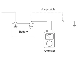
| 5. |
Read the current value of the ammeter.
|
| Cleaning |
| 1. |
Make sure the ignition switch and all accessories are in the OFF position. |
| 2. |
Disconnect the battery cables (negative first). |
| 3. |
Remove the battery from the vehicle.
|

| 4. |
Inspect the battery tray for damage caused by the loss of
electrolyte. If acid damage is present, it will be necessary to clean
the area with a solution of clean warm water and baking soda. Scrub the
area with a stiff brush and wipe off with a cloth moistened with
baking soda and water. |
| 5. |
Clean the top of the battery with the same solution as described above. |
| 6. |
Inspect the battery case and cover for cracks. If cracks are present, the battery must be replaced. |
| 7. |
Clean the battery posts with a suitable battery post tool. |
| 8. |
Clean the inside surface of the terminal clamps with a
suitable battery cleaning tool. Replace damaged or frayed cables and
broken terminal clamps. |
| 9. |
Install the battery in the vehicle. |
| 10. |
Connect the cable terminals to the battery post, making sure tops of the terminals are flush with the tops of the posts . |
| 11. |
Tighten the terminal nuts securely. |
| 12. |
Coat all connections with light mineral grease after tightening.
|
Components 1. Battery insulation pad2. Battery3. Battery tray4. Battery mounting bracket
Troubleshooting
Other information:
Kia Cadenza YG 2016-2021 Service Manual: Photo Sensor Repair procedures
Inspection 1. Ignition "ON" 2. Using the scan tool. 3. Emit intensive light toward photo sensor using a lamp, and check the output voltage change. 4. The voltage will rise with higher intensive light and reduce with lower intensive light.
Kia Cadenza YG 2016-2021 Service Manual: Heater & A/C Control Unit (DATC) Components and Components Location
C
Categories
- Manuals Home
- Kia Cadenza Owners Manual
- Kia Cadenza Service Manual
- Suspension System
- Restraint
- General Information
- New on site
- Most important about car

Copyright © 2026 www.kcadenzavg.com - 0.0361