Kia Cadenza YG: BCM (Body Control Module) / Body Control Module (BCM) Repair procedures
| Removal |
| 1. |
Disconnect the negative (-) battery terminal. |
| 2. |
Remove the crash pad lower panel (A).
|

| 3. |
Remove the Reinforcing panel after loosening the mounting bolt and nut.
(Refer to Body - " Crash Pad") |
| 4. |
Disconnect the IPM connectors, loosening the nuts(2EA) and bolt (1EA).
|
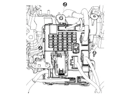
| 5. |
Disconnect the rear connector, and then remove the IPM. |
| Installation |
| 1. |
Install the IPM. |
| 2. |
Install the reinforcing panel. |
| 3. |
Install the crash pad lower panel. |
| 4. |
Disconnect the negative (-) battery terminal. |
| IPM Diagnosis With GDS |
| 1. |
It will be able to diagnose defects of IPM with GDS quickly.
GDS can operates actuator forcefully, input/output value monitoring and
self diagnosis. |
| 2. |
Select model and "IPM". |
| 3. |
Select the module to check. |
| 4. |
Select "Input/output monitoring", if you will check current
data of body network system. It provides input/output status of each
module.
|

| 5. |
If you will check each module data operation forcefully, select "Actuation test".
|

| 6. |
To check the DTC of the each module, select "DIAGNOSTIC TROUBLE CODES".
|

| 7. |
If you want to change user option, select “user option”.
|

IPM Overview The Body Control Module (IPM-Intelligent integrated Platform Module) supplies vehicle occupants with visual and audible information and controls various vehicle functions.
Other information:
Kia Cadenza YG 2016-2021 Service Manual: Schematic Diagrams
Circuit Diagram SVM System Input/Output 1. Camera input ItemSpecificationLens angle of view190 degreesAngle of viewHorizontal186 degreesVertical135 degreesFunctionProvides the original image of the wide angle image (no additional function)Application locationSame camera applied to the front, rear, left and right 2.
Kia Cadenza YG 2016-2021 Service Manual: Description and Operation
Description System Overview The System offers the following features: – Human / machine interface through a 1-stage button, for terminal switching and engine start. – Control of external relays for ACC / IGN1 / IGN2 terminal switching and STARTER, without use of mechanical ignition switch.
Categories
- Manuals Home
- Kia Cadenza Owners Manual
- Kia Cadenza Service Manual
- Brake System
- Steering System
- Alternator Schematic Diagrams
- New on site
- Most important about car
