Kia Cadenza YG: Engine Control System / Camshaft Position Sensor (CMPS) Repair procedures
| Inspection |
| 1. |
Check the signal waveform of the CMPS and CKPS using the GDS.
|
| Removal |
|

| 1. |
Turn the ignition switch OFF and disconnect the battery negative (-) cable. |
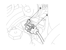
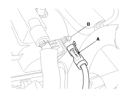
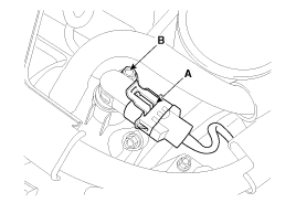
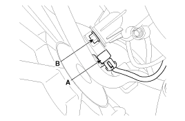
| 2. |
Disconnect the camshaft position sensor connector (A). |
| 3. |
Remove the installation bolt (B), and then vertically remove the sensor from the cylinder head.
[Bank 1/Intake]
[Bank 1/Exhaust]
[Bank 2/Intake]
[Bank 2/Exhaust]
|
| Installation |
|

|
|
|
| 1. |
Install in the reverse order of removal.
|
Circuit Diagram
Description Knocking is a phenomenon characterized by undesirable vibration and noise and can cause engine damage. The two Knock Sensor (KS) are installed inside the V-valley of the cylinder block and senses engine knocking.
Other information:
Kia Cadenza YG 2016-2021 Service Manual: Lane Departure Warning System (LDWS) Unit Repair procedures
Removal 1. Disconnect the negative (-) battery terminal. 2. Remove the LDWS unit cover (A). 3. Remove the LDWS unit connector (A). 4. Remove the LDWS unit after widening the mounting clips. Installation 1. Install the LDWS unit. 2.
Kia Cadenza YG 2016-2021 Service Manual: A/C Pressure Transducer Description and Operation
Description A/C pressure transducer convert the pressure value of high pressure line into voltage value after measure it. By converted voltage value, engine ECU controls cooling fan by operating it high speed or low speed. Engine ECU stop the operation of compressor when the temperature of refrigerant line is so high or so low irregularl
Categories
- Manuals Home
- Kia Cadenza Owners Manual
- Kia Cadenza Service Manual
- General Information
- Engine Mechanical System
- Engine Control / Fuel System
- New on site
- Most important about car
