Kia Cadenza YG: Emission Control System / Components and Components Location
| Components Location |
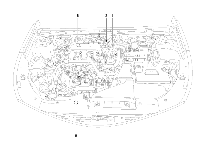
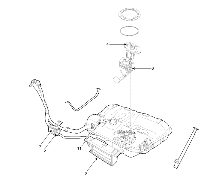
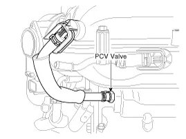
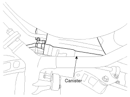
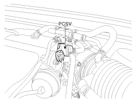
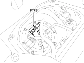
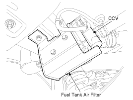
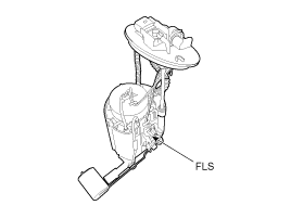
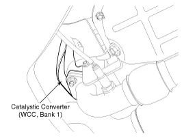
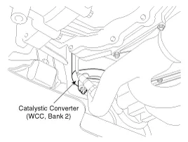
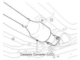
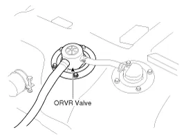
| 1. PCV Valve 2. Canister 3. Purge Control Solenoid Valve (PCSV) 4. Fuel Tank Pressure Sensor (FTPS) 5. Canister Close Valve (CCV) 6. Fuel Level Sender (FLS) | 7. Fuel Tank Air Filter 8. Catalytic Converter (WCC, Bank 1) 9. Catalytic Converter (WCC, Bank 2) 10. Catalytic Converter (UCC) 11. On-board Refueling Vapor Recovery (ORVR) Valve |
| 1. PCV Valve | 2. Canister |
|
|
| 3. Purge Control Solenoid Valve (PCSV) | 4. Fuel Tank Pressure Sensor (FTPS) |
|
|
| 5. Canister Close Valve (CCV) 7. Fuel Tank Air Filter | 6. Fuel Level Sender (FLS) |
|
|
| 8. Catalytic Converter (WCC, Bank 1) | 9. Catalytic Converter (WCC, Bank 2) |
|
|
| 10. Catalytic Converter (UCC) | 11. On-board Refueling Vapor Recovery (ORVR) Valve |
|
|
Specifications Purge Control Solenoid Valve (PCSV) ▷ Specification ItemSpecificationCoil Resistance (Ω)22.0 ~ 26.0 [20°C(68°F)] Fuel Tank Pressure Sensor (FTPS) ▷ Type: Piezo-Resistive Pressure Sensor ▷ Specification Pressure (kPa)Output Voltage (V)-6.
Description Emissions Control System consists of three major systems. • Crankcase Emission Control System prevents blow-by gas from releasing into the atmosphere.
Other information:
Kia Cadenza YG 2016-2021 Service Manual: Surround View Monitoring Unit Repair procedures
Removal 1. Disconnect the negative (-) battery terminal. 2. Remove the glove box housing. (Refer to Body - "Glove Box Housing") 3. Remove the SVM unit (B) after disconnecting the connectors (A) and mounting bolts. Installation 1. Install the SVM unit.
Kia Cadenza YG 2016-2021 Service Manual: Troubleshooting
Troubleshooting Examples of False-Alarm Occurrence from system characteristics (It’s not a problem) – Characteristics of EM Wave : EM Waves are reflected against all material and especially metal very well. Reflections of EM Waves are varies with the shape of object.
Categories
- Manuals Home
- Kia Cadenza Owners Manual
- Kia Cadenza Service Manual
- Rail Pressure Sensor (RPS) Schematic Diagrams
- Components and Components Location
- General Information
- New on site
- Most important about car
