Kia Cadenza YG: Interior / Console Repair procedures
| Replacement |
|

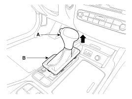
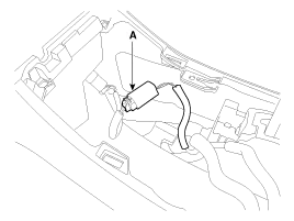
| 1. |
Using a screwdriver or remover, remove the gear boots (B). |
| 2. |
To remove the gear knob (A) and gear boots (B) pull both of it up.
|
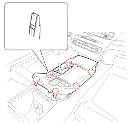
| 3. |
Using a screwdriver or remover, remove the floor console upper cover (A).
|
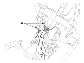
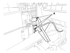
| 4. |
Disconnect the connectors (A) from the floor console upper cover .
[Rear]
[Front]
|
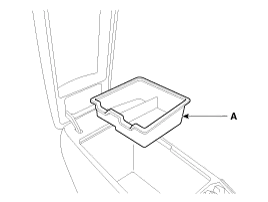
| 5. |
Remove the console armrest tray (A).
|
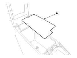
| 6. |
Remove the console tray met (A).
|
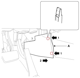
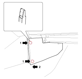
| 7. |
Using a screwdriver or remover, remove the console side cover (A).
[LH]
[RH]
|
| 8. |
Disconnect the rear power outlet connector (A).
|
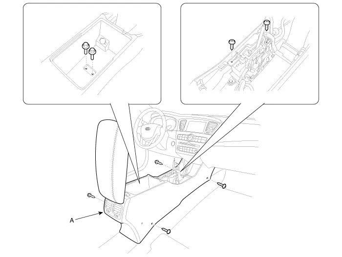
| 9. |
After loosening the mounting screws and bolts, then remove the floor console assembly (A).
|
| 10. |
Installation is the reverse of removal.
|
|
| 1. |
Remove the floor console assembly. |
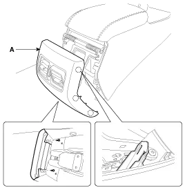
| 2. |
After loosening the mounting screws, then remove the rear console cover (A).
|
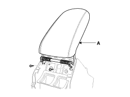
| 3. |
After loosening the mounting screws, then remove the console armrest (A).
|
| 4. |
Installation is the reverse of removal.
|
Components 1. Gear knob & boots 2. Floor console upper cover3. Floor console upper cover tray4. Console side cover [LH]5. Console side cover [RH]6.
Components 1. Main crash pad assembly2. Crash pad side cover3. Side airvent duct4. Crash pad garnish (LH)5. Cluster fascia panel6. Shroud upper panel7.
Other information:
Kia Cadenza YG 2016-2021 Service Manual: Description and Operation
Description Back view camera will activate when the backup light is ON with the ignition switch ON and the shift lever in the R position. This system is a supplemental system that shows behind the vehicle through the ECM (Reverse Display Room Mirror) mirror or AVN head unit while backing-up.
Kia Cadenza YG 2016-2021 Service Manual: Repair procedures
Removal 1. Remove the trunk trim in the trunk after removing the screws and clips. (Refer to Body - "Trunk") 2. Remove the camera holder (A) as shown arrow direction, and then remove the back view camera (B). Installation 1. Install the back view camera and camera holder.
Categories
- Manuals Home
- Kia Cadenza Owners Manual
- Kia Cadenza Service Manual
- Engine Control / Fuel System
- Body (Interior and Exterior)
- Battery Troubleshooting
- New on site
- Most important about car
