Kia Cadenza YG: Interior / Crash Pad Components and Components Location
Kia Cadenza YG 2016-2021 Service Manual / Body (Interior and Exterior) / Interior / Crash Pad Components and Components Location
| Components |
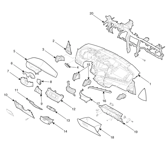
| 1. Main crash pad assembly 2. Crash pad side cover 3. Side airvent duct 4. Crash pad garnish (LH) 5. Cluster fascia panel 6. Shroud upper panel 7. Shroud lower panel | 8. Crash pad center garnish 9. Ignition key grommet 10. Crash pad lower panel 11. Reinforcing panel 12. Center facia upper panel 13. Digital clock 14. Center facia lower tray | 15. Center airvent duct 16. Crash pad garnish (RH) 17. Center crash pad side cover 18. Glove box 19. Glove box housing 20. Cowl cross bar assembly |
Replacement Floor Console Replacement • When prying with a flat-tip screwdriver, wrap it with protective tape, and apply protective tape around the related parts, to prevent damage.
Replacement Cluster Replacement • When prying with a flat-tip screwdriver, wrap it with protective tape, and apply protective tape around the related parts, to prevent damage.
Other information:
Kia Cadenza YG 2016-2021 Service Manual: Start/Stop Button Repair procedures
Removal 1. Disconnect the negative (-) battery terminal. 2. Using a screw driver or remover, remove the center fascia lower panel (A). 3. Remove the in-car hose (A) and disconnect the connectors (B) from the heater & A/C control unit. 4.
Kia Cadenza YG 2016-2021 Service Manual: Heater & A/C Control Unit (DATC) Components and Components Location
C
Categories
- Manuals Home
- Kia Cadenza Owners Manual
- Kia Cadenza Service Manual
- Brake System
- Body Electrical System
- Emission Control System
- New on site
- Most important about car

Copyright © 2026 www.kcadenzavg.com - 0.0258