
Kia Cadenza YG: Engine Control System / CVVT Oil Temperature Sensor (OTS) Repair procedures
Kia Cadenza YG 2016-2021 Service Manual / Engine Control / Fuel System / Engine Control System / CVVT Oil Temperature Sensor (OTS) Repair procedures
| Inspection |
| 1. |
Turn the ignition switch OFF. |
| 2. |
Disconnect the OTS connector. |
| 3. |
Remove the OTS. (Refer to "Removal") |
| 4. |
After immersing the thermistor of the sensor into engine coolant, measure resistance between the OTS terminals 1 and 2. |
| 5. |
Check that the resistance is within the specification.
|
| Removal |
| 1. |
Turn the ignition switch OFF and disconnect the battery negative (-) cable. |
| 2. |
Remove the air cleaner assembly.
(Refer to Engine Mechanical System - "Air Cleaner") |
| 3. |
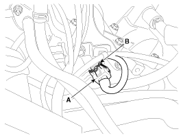
Disconnect the connector (A), and then remove the CVVT oil temperature sensor (B).
|
| Installation |
|

|
|
| 1. |
Install in the reverse order of removal.
|
Circuit Diagram
Description Accelerator Position Sensor (APS) is installed on the accelerator pedal module and detects the rotation angle of the accelerator pedal.
Other information:
Kia Cadenza YG 2016-2021 Service Manual: Components and Components Location
C
Kia Cadenza YG 2016-2021 Service Manual: Specifications
Specification ItemSpecificationUltrasonic sensorVoltage ratingDC 12 VDetecting range30 cm ~ 120 cmOperation voltageDC 9 ~ 16 VOperation currentMAX 300 mAOperation temperature-30°C ~ +80°C (-22°C ~ +176°C)Operation frequency48 ± 5 KHzEffective operating velocity10 KPH (6.
Categories
- Manuals Home
- Kia Cadenza Owners Manual
- Kia Cadenza Service Manual
- Battery Troubleshooting
- Body Electrical System
- Restraint
- New on site
- Most important about car

Copyright © 2026 www.kcadenzavg.com - 0.0257