Kia Cadenza YG: Engine Control System / Engine Coolant Temperature Sensor (ECTS) Schematic Diagrams
| Circuit Diagram |
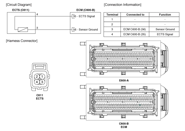
Specification TemperatureResistance (kΩ)°C°F-40-4048.14-20-414.13 ~ 16.830325.7920682.31 ~ 2.59401041.15601400.59801760.32
Inspection 1. Turn the ignition switch OFF. 2. Disconnect the ECTS connector. 3. Remove the ECTS (Refer to "Removal"). 4. After immersing the thermistor of the sensor into engine coolant, measure resistance between the ECTS terminals 3 and 4.
Other information:
Kia Cadenza YG 2016-2021 Service Manual: Description and Operation
Description Adaptive Front-lighting System (AFLS) AFLS(Adaptive Front-lighting System)is a headlamp orientation control system that takes into account both steering angle and vehicle speed to orient the headlamps to an angle that provides better nighttime visibility.
Kia Cadenza YG 2016-2021 Service Manual: Troubleshooting
Troubleshooting Problem Symptoms Table Before replacing or repairing air conditioning components, first determine if the malfunction is due to the refrigerant charge, air flow or compressor. Use the table below to help you find the cause of the problem.
Categories
- Manuals Home
- Kia Cadenza Owners Manual
- Kia Cadenza Service Manual
- Brake System
- Timing Chain Repair procedures
- Engine Control / Fuel System
- New on site
- Most important about car
