Kia Cadenza YG: Intake And Exhaust System / Exhaust Manifold Repair procedures
| Removal and Installation |
| [LH] |
| 1. |
Disconnect the LH front and rear heated oxygen sensor (HO2S) connector.
(Refer to Fuel System - "Heated Oxygen Sensor (HO2S)") |
| 2. |
Remove the front muffler.
(Refer to Intake And Exhaust System - "Muffler") |
| 3. |
Remove the cooling fan assembly.
(Refer to Cooling System - "Cooling Fan") |
| 4. |
Remove oil level gauge assembly.
(Refer to Lubrication System - "Oil Level Gauge & Pipe") |
| 5. |
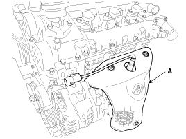
Remove the LH exhaust manifold heat protector (A).
|
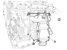
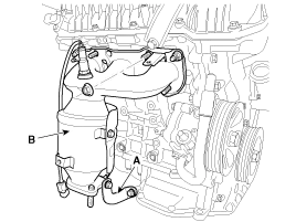
| 6. |
Remove the LH exhaust manifolds stay (A),and then remove the LH exhaust manifold (B) and gasket.
|
| 7. |
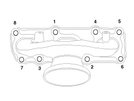
Install in the reverse order of removal.
|

| [RH] |
| 1. |
Disconnect the RH front and rear heated oxygen sensor (HO2S) connector.
(Refer to Fuel System - "Heated Oxygen Sensor (HO2S)") |
| 2. |
Remove the surge tank.
(Refer to Intake And Exhaust System - "Surge Tank") |
| 3. |
Remove the front muffler.
(Refer to Intake And Exhaust System - "Muffler") |
| 4. |
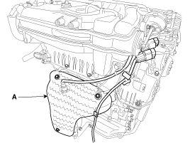
Remove the RH exhaust manifold heat protector (A).
|
| 5. |
Remove the RH exhaust manifolds stay (A),and then remove the RH exhaust manifold (B) and gasket.
|
| 6. |
Install in the reverse order of removal.
|

Components 1. LH Exhaust manifold gasket2. LH Exhaust manifold3. LH Heat protector4. LH Exhaust manifold stay5. RH Exhaust manifold gasket6. RH Exhaust manifold7.
Removal and Installation VIS 1 [Intake Manifold] 1. Disconnect the battery "-" terminal. 2. Remove the engine cover. 3. Disconnect the VIS actuator hose (A).
Other information:
Kia Cadenza YG 2016-2021 Service Manual: Adaptive Front Lighting System Repair procedures
Removal 1. Disconnect the negative (-) battery terminal. 2. Using a screwdriver or remover, remove the crash pad side cover (A). [RH] 3. Disconnect the stopper (B) from the glove box (A). 4. Disconnect the air damper (A) from the glove box (B).
Kia Cadenza YG 2016-2021 Service Manual: Auto defoging sensor Repair procedures
Inspection 1. Press the OFF switch more then 4 times within 2 seconds while pressing the MODE switch. DisplayFail description00Normal23Auto defog sensor OPEN24Auto defog sensor SHORT43Defog door potentiometer OPEN/SHORT44Defog door potentiometer * Diagnostic procedure refer to DTC code.
Categories
- Manuals Home
- Kia Cadenza Owners Manual
- Kia Cadenza Service Manual
- Emission Control System
- General Information
- Rail Pressure Sensor (RPS) Schematic Diagrams
- New on site
- Most important about car
