Kia Cadenza YG: Intake And Exhaust System / Variable Intake Solenoid(VIS) Actuator Repair procedures
| Removal and Installation |
| 1. |
Disconnect the battery "-" terminal. |
| 2. |
Remove the engine cover. |
| 3. |
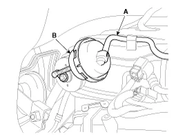
Disconnect the VIS actuator hose (A). |
| 4. |
Remove the VIS actuator (B).
|
| 5. |
Install in the reverse order of removal. |
| 1. |
Disconnect the battery "-" terminal. |
| 2. |
Remove the engine cover. |
| 3. |
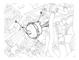
Disconnect the VIS actuator hose (A). |
| 4. |
Remove the VIS actuator (B).
|
| 5. |
Install in the reverse order of removal. |
Removal and Installation [LH] 1. Disconnect the LH front and rear heated oxygen sensor (HO2S) connector. (Refer to Fuel System - "Heated Oxygen Sensor (HO2S)") 2.
Components 1. Front muffler2. Catalytic converter & center muffler assembly3. Main muffler4. Gasket5. Hanger
Other information:
Kia Cadenza YG 2016-2021 Service Manual: Adaptive Front Lighting System Repair procedures
Removal 1. Disconnect the negative (-) battery terminal. 2. Using a screwdriver or remover, remove the crash pad side cover (A). [RH] 3. Disconnect the stopper (B) from the glove box (A). 4. Disconnect the air damper (A) from the glove box (B).
Kia Cadenza YG 2016-2021 Service Manual: Heater Unit Repair procedures
Replacement 1. Disconnect the negative (-) battery terminal. 2. Recover the refrigerant with a recovery/ recycling/ charging station. 3. When the engine is cool, drain the engine coolant from the radiator. 4. Remove the expansion valve cover (A).
Categories
- Manuals Home
- Kia Cadenza Owners Manual
- Kia Cadenza Service Manual
- Engine Mechanical System
- Brake System
- Restraint
- New on site
- Most important about car
