Kia Cadenza YG: Intake And Exhaust System / Exhaust Manifold Components and Components Location
| Components |
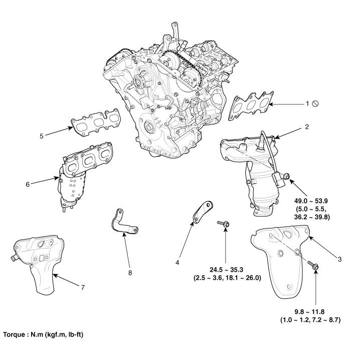
| 1. LH Exhaust manifold gasket 2. LH Exhaust manifold 3. LH Heat protector 4. LH Exhaust manifold stay | 5. RH Exhaust manifold gasket 6. RH Exhaust manifold 7. RH Heat protector 8. RH Exhaust manifold stay |
Removal and Installation 1. Remove the surge tank. (Refer to Intake And Exhaust System - "Surge Tank") 2. Remove the low pressure fule line. (Refer to Fuel System - "Fuel Line") 3.
Removal and Installation [LH] 1. Disconnect the LH front and rear heated oxygen sensor (HO2S) connector. (Refer to Fuel System - "Heated Oxygen Sensor (HO2S)") 2.
Other information:
Kia Cadenza YG 2016-2021 Service Manual: Compressor Repair procedures
Removal 1. If the compressor is marginally operable, run the engine at idle speed, and let the air conditioning work for a few minutes, then shut the engine off. 2. Disconnect the negative cable from the battery. 3. Recover the refrigerant with a recovery/charging station.
Kia Cadenza YG 2016-2021 Service Manual: Blower Unit Components and Components Location
Component Location Components 1. Duct Seal2. Duct Case3. Inlet Door4. Intake Actuator5. Inlet Duct Case (A)6. Climate control air filter7. Cluster Ionizer8. Climate control air filter Cover9. Blower Upper Case10. Blower Lower Case11. FET12. Resistor13.
Categories
- Manuals Home
- Kia Cadenza Owners Manual
- Kia Cadenza Service Manual
- Components and Components Location
- General Information
- Body (Interior and Exterior)
- New on site
- Most important about car
