Kia Cadenza YG: Driveshaft Assembly / Front Driveshaft Components and Components Location
Kia Cadenza YG 2016-2021 Service Manual / Driveshaft and axle / Driveshaft Assembly / Front Driveshaft Components and Components Location
| Component Location |
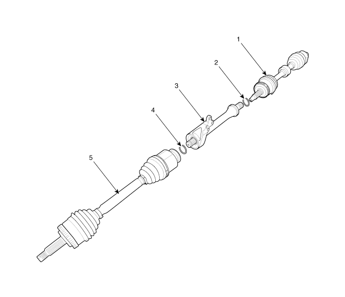
| 1. Driveshaft(LH) 2. Circlip 3. Inner shaft bearing bracket assembly | 4. Circlip 5. Driveshaft(RH)6. |
| Components |
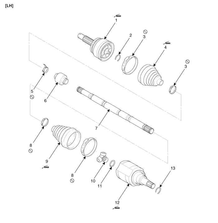
| 1. BJ Assembly 2. Clip 3. BJ Boot Band 4. BJ Boot | 5. Dynamic Damper Band 6. Dynamic Damper 7. Shaft 8. UTJ Boot Band | 9. UTJ Boot 10. Spider Assembly 11. Clip 12. UTJ Case | 13.Clip |
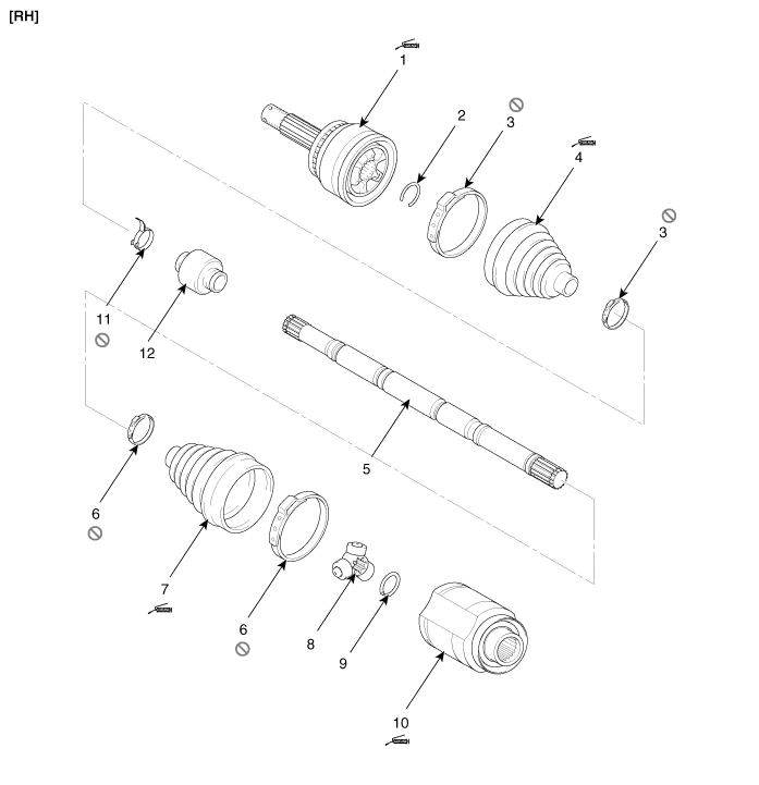
| 1. BJ Assembly 2. Clip 3. BJ Boot Band 4. BJ Boot | 5. Shaft 6. UTJ Boot Band 7. UTJ Boot 8. Spider Assembly | 9. Clip 10. UTJ Case 11. Dynamic Damper Band 12. Dynamic Damper |
Replacement 1. Loosen the wheel nuts slightly. Raise the vehicle, and make sure it is securely supported. 2. Remove the front wheel and tire (A) from front hub.
Other information:
Kia Cadenza YG 2016-2021 Service Manual: Components and Components Location
C
Kia Cadenza YG 2016-2021 Service Manual: Blind Spot Detection Radar Calibration Description and Operation
Description To sense the cars exactly in the next lane with the radar, the direction of the sensor and the direction of the vehicle have to align. This is BSD unit alignment. If this alignment is not performed as below illustration, the degradation of detection performance and the cause of false alarms.
Categories
- Manuals Home
- Kia Cadenza Owners Manual
- Kia Cadenza Service Manual
- Body Electrical System
- General Information
- Steering System
- New on site
- Most important about car

Copyright © 2026 www.kcadenzavg.com - 0.0254